Install a memory module
Memory modules are installed in the system boards that are accessed from the front of the server.

See Memory module installation rules and order for detailed information about memory configuration and setup.
If you are installing an optional processor, install it before installing memory modules. See Install a processor-heat-sink module
See Lenovo ServerProven website for a list of all the memory module types and capacities that are supported for your server.
Do not mix RDIMMs and LR-DIMMs in the same server.
Install higher capacity (ranked) DIMMs first, following the population sequence for the memory mode being used.
Installing or removing DIMMs changes the server configuration. When you restart the server, it displays a message that indicates that the memory configuration has changed. There are multiple ways to view the server configuration. See Management options for a description of each management method and how each method applies to various deployment situations.
If the front cover is installed, remove it. See Remove the front cover.
Remove the compute tray with the system board where you are installing the memory module. See Remove a compute tray.
If you are installing a memory module in the lower compute system board, remove the upper system board or system board filler. See Remove a system board.
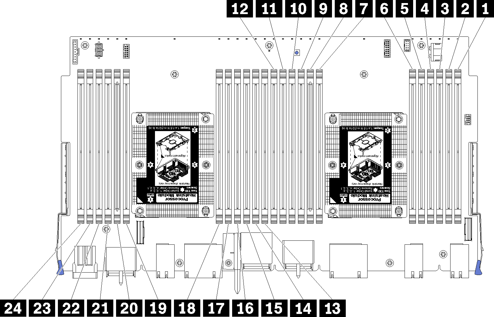
| DIMM number | System board 1 (lower board, lower tray) DIMM number | System board 2 (upper board, lower tray) DIMM number | System board 3 (lower board, upper tray) DIMM number | System board 4 (upper board, upper tray) DIMM number |
|---|---|---|---|---|
| 1 | 1 | 25 | 49 | 73 |
| 2 | 2 | 26 | 50 | 74 |
| 3 | 3 | 27 | 51 | 75 |
| 4 | 4 | 28 | 52 | 76 |
| 5 | 5 | 29 | 53 | 77 |
| 6 | 6 | 30 | 54 | 78 |
| 7 | 7 | 31 | 55 | 79 |
| 8 | 8 | 32 | 56 | 80 |
| 9 | 9 | 33 | 57 | 81 |
| 10 | 10 | 34 | 58 | 82 |
| 11 | 11 | 35 | 59 | 83 |
| 12 | 12 | 36 | 60 | 84 |
| 13 | 13 | 37 | 61 | 85 |
| 14 | 14 | 38 | 62 | 86 |
| 15 | 15 | 39 | 63 | 87 |
| 16 | 16 | 40 | 64 | 88 |
| 17 | 17 | 41 | 65 | 89 |
| 18 | 18 | 42 | 66 | 90 |
| 19 | 19 | 43 | 67 | 91 |
| 20 | 20 | 44 | 68 | 92 |
| 21 | 21 | 45 | 69 | 93 |
| 22 | 22 | 46 | 70 | 94 |
| 23 | 23 | 47 | 71 | 95 |
| 24 | 24 | 48 | 72 | 96 |
Complete the following steps to install a memory module:
Always wear an electrostatic-discharge strap when removing or installing memory modules. Electrostatic-discharge gloves can also be used.
Never hold two or more memory modules together so that they touch. Do not stack memory modules directly on top of each other during storage.
Never touch the gold memory module connector contacts or allow these contacts to touch the outside of the memory-module connector housing.
Handle memory modules with care: never bend, twist, or drop a memory module.
- Install the memory module.Figure 2. Memory module installation
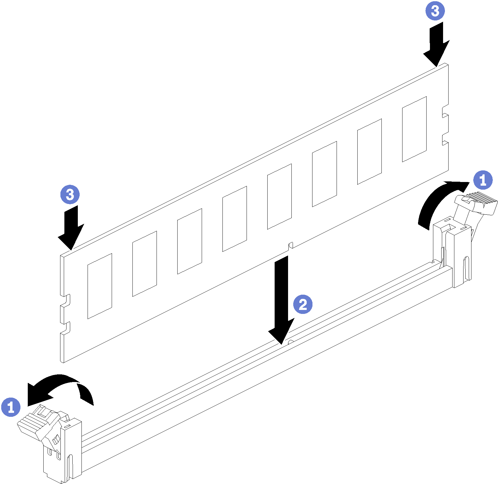
- Open the memory module connector retaining clips. If a memory module is already installed in the connector, remove it.
- Align the keys on the memory module that you are installing with the connector; then, insert the memory module.
- Firmly press both ends of the memory module straight down into the connector until the retaining clips snap into the locked position.
Install the upper system board or system board filler, if it was removed. See Install a system board.
Install the compute tray . See Install a compute tray.
If you have no additional options to install in the upper or lower compute tray, install the front cover. See Install the front cover.
Demo video