Install a processor-heat-sink module
Processors are in the system boards that are accessed from the front of the server. The processor and heat sink are removed together as part of a processor-heat-sink-module (PHM) assembly. PHM installation requires a Torx T30 driver.


Each processor socket must always contain a cover or a PHM. When removing or installing a PHM, protect empty processor sockets with a cover.
Do not touch the processor socket or processor contacts. Processor-socket contacts are very fragile and easily damaged. Contaminants on the processor contacts, such as oil from your skin, can cause connection failures.
Remove and install only one PHM at a time. If the system board supports multiple processors, install the PHMs starting with the first processor socket.
Do not allow the thermal grease on the processor or heat sink to come in contact with anything. Contact with any surface can compromise the thermal grease, rendering it ineffective. Thermal grease can damage components, such as electrical connectors in the processor socket. Do not remove the grease cover from a heat sink until you are instructed to do so.
To ensure the best performance, check the manufacturing date on the new heat sink and make sure it does not exceed 2 years. Otherwise, wipe off the existing thermal grease and apply the new grease onto it for optimal thermal performance.
PHMs are keyed for the socket where they can be installed and for their orientation in the socket.
See Lenovo ServerProven website for a list of processors supported for your server. All processors on the system board must have the same speed, number of cores, and frequency.
Before you install a new PHM or replacement processor, update your system firmware to the latest level. See Update the firmware.
Installing an additional PHM can change the memory requirements for your system. See Install a memory module for a list of processor-to-memory relationships.
Optional devices available for your system might have specific processor requirements. See the documentation that comes with the optional device for information.
Remove the front cover. See Remove the front cover.
Remove the compute tray where the system board is installed. See Remove a compute tray.
If you are installing a PHM in the lower system board, remove the upper system board or system board filler. See Remove a system board.
Complete the following steps to install a PHM.
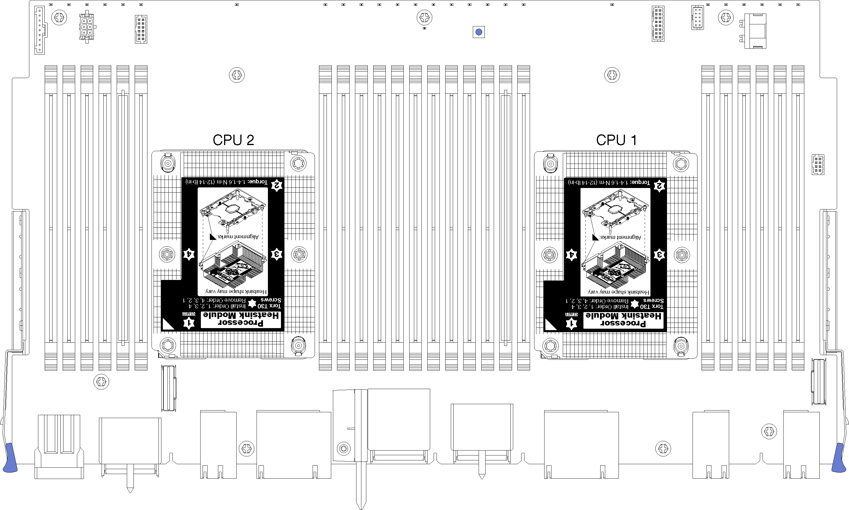
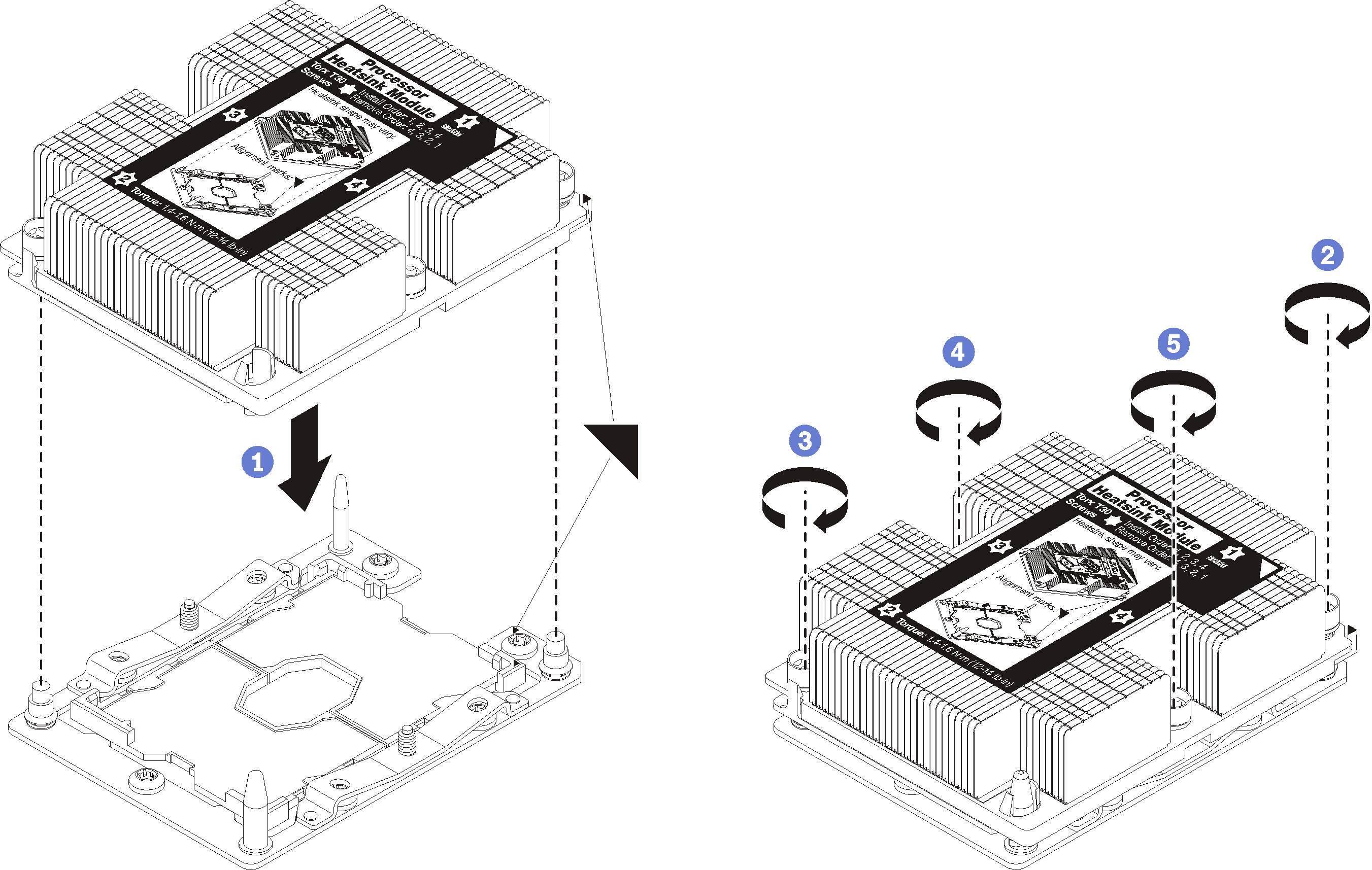
- Install the processor-heat-sink module on the system board.Figure 3. Installing a PHM
If there are memory modules to install, install them. See Install a memory module. Also install memory module fillers, that are provided with the PHM, in any vacant memory module connectors.
Install the upper system board or system board filler, if it was removed. See Install a system board.
Install the compute tray . See Install a compute tray.
If you have no additional options to install in the upper or lower compute tray, install the front cover. See Install the front cover.
Demo video