Front I/O module
The front I/O module of the server provides controls, connectors, and LEDs. The front I/O module varies by model.
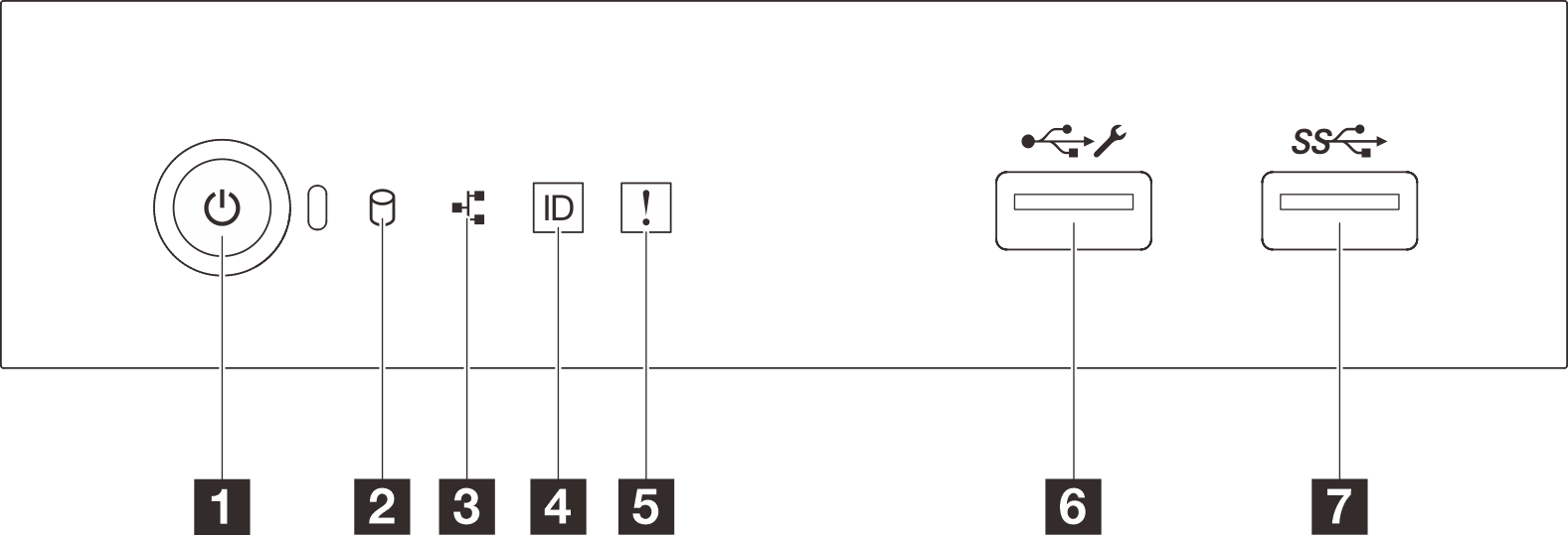
| Callout | Callout |
|---|---|
| 1 Power button/LED (green) | 5 System error LED (yellow) |
| 2 Drive activity LED (green) Note For onboard SATA indication only | 6 USB 2.0 connector with Lenovo XClarity Controller management |
| 3 Network activity LED (green) Note For onboard LAN indication only | 7 USB 3.2 Gen 1 connector |
| 4 System ID button/LED (blue) |
2 Drive activity LED (green)
| Status | Color | Description |
|---|---|---|
| Solid on | Green | The drive is active. |
| Flashing | Green | The drive is being accessed. |
| Off | None | The drive is not active. |
3 Network activity LED (green)
The network activity LED helps you identify the network connectivity and activity.
| Status | Color | Description |
|---|---|---|
| On | Green | The server is connected to a network. |
| Blinking | Green | The network is connected and active. |
| Off | None | The server is disconnected from the network. |
4 System ID button/LED (blue)
Use this system ID button and the blue system ID LED to visually locate the server. Each time you press the system ID button, the state of the system ID LED changes. The LED can be changed to on, blinking, or off. You can also use the Lenovo XClarity Controller or a remote management program to change the state of the system ID LED to assist in visually locating the server among other servers.
If the XClarity Controller USB connector is set to have both the USB 2.0 function and XClarity Controller management function, you can press the system ID button for three seconds to switch between the two functions.
5 System error LED (yellow)
The system error LED provides basic diagnostic functions for your server.
| Status | Color | Description | Action |
|---|---|---|---|
| On | Yellow | An error has been detected on the server. Causes might include one or more of the following errors:
| Check system logs or internal error LEDs to identify the failed part. |
| Off | None | The server is off or the server is on and is working correctly. | None. |
6 USB 2.0 connector with Lenovo XClarity Controller management
Connect a USB 2.0 device, such as a mouse, keyboard, or other devices, to this connector.
Connection to Lenovo XClarity Controller is primarily intended for users with a mobile device running the Lenovo XClarity Controller mobile application. When a mobile device is connected to this USB port, an Ethernet over USB connection is established between the mobile application running on the device and the Lenovo XClarity Controller.
Select Network in BMC Configuration to view or modify settings.
Four types of settings are available:
Host only mode
In this mode, the USB port is always solely connected to the server.
BMC only mode
In this mode, the USB port is always solely connected to Lenovo XClarity Controller.
Shared mode: owned by BMC
In this mode, connection to the USB port is shared by the server and Lenovo XClarity Controller, while the port is switched to Lenovo XClarity Controller.
Shared mode: owned by host
In this mode, connection to the USB port is shared by the server and Lenovo XClarity Controller, while the port is switched to the server.
For more information, see Set USB port for Lenovo XClarity Controller connection.
7 USB 3.2 Gen 1 (5GB) connector
Used to attach a device that requires a USB 2.0 or 3.0 connection, such as a keyboard, a mouse, or a USB flash drive.