Install a simple-swap drive (bay 1-2)
Follow this procedure to install a simple-swap drive to bay 1 or bay 2.
Read Safety inspection checklist and Installation guidelines to ensure that you work safely.
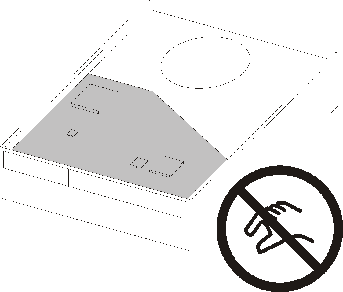
Touch the static-protective package that contains the component to any unpainted metal surface on the server; then, remove it from the package and place it on a static-protective surface.
Make sure the type of drives to be installed is supported. Following are the types supported:
- 3.5-inch simple-swap hard-disk drive or solid-state drive in drive bay 1 and drive bay 3
- 2.5-inch simple-swap solid-state drive in drive bay 2
For a complete list of supported optional devices for the server, see Lenovo ServerProven website.
If there are more than one drives to be installed, determine installation order based on the following rules:
Start with solid-state drives, and proceed with hard-disk drives.
When installing one 3.5-inch solid-state drive and one 3.5-inch hard-disk drive, install the solid-state drive in bay 1 and the hard-disk drive in bay 3.
Start with the drive with the lowest capacity.
Start with bay 1, proceed to bay 2, and bay 3.
NoteDrives of different types and different capacities are allowed to be installed in one server, but not in the same RAID array. The drives in a single RAID array must be the same type and the same capacity. SeeRAID Setup for more details.
- A video of this procedure is available at YouTube.
Procedure
- Install a 3.5-inch or 2.5-inch drive to the retainer
 Slightly tear both sides of the retainer apart.
 Align the four holes on the drive with the corresponding pins on the retainer; then, fit the drive into the retainer.NoteThe drive connectors should face the retainer handles.Install a 3.5-inch drive into the retainerFigure 2. Installing a 3.5-inch drive into the retainer
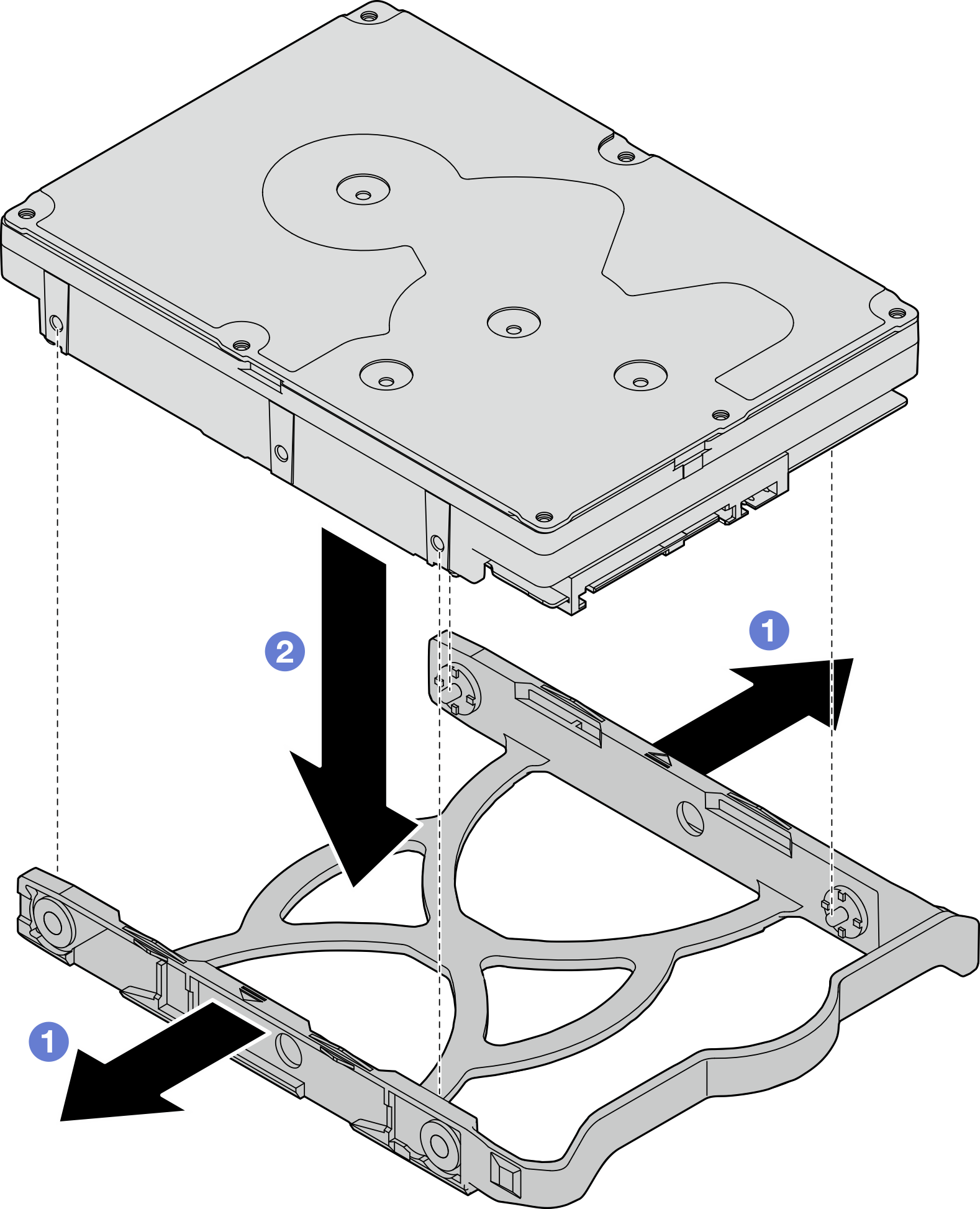 Note
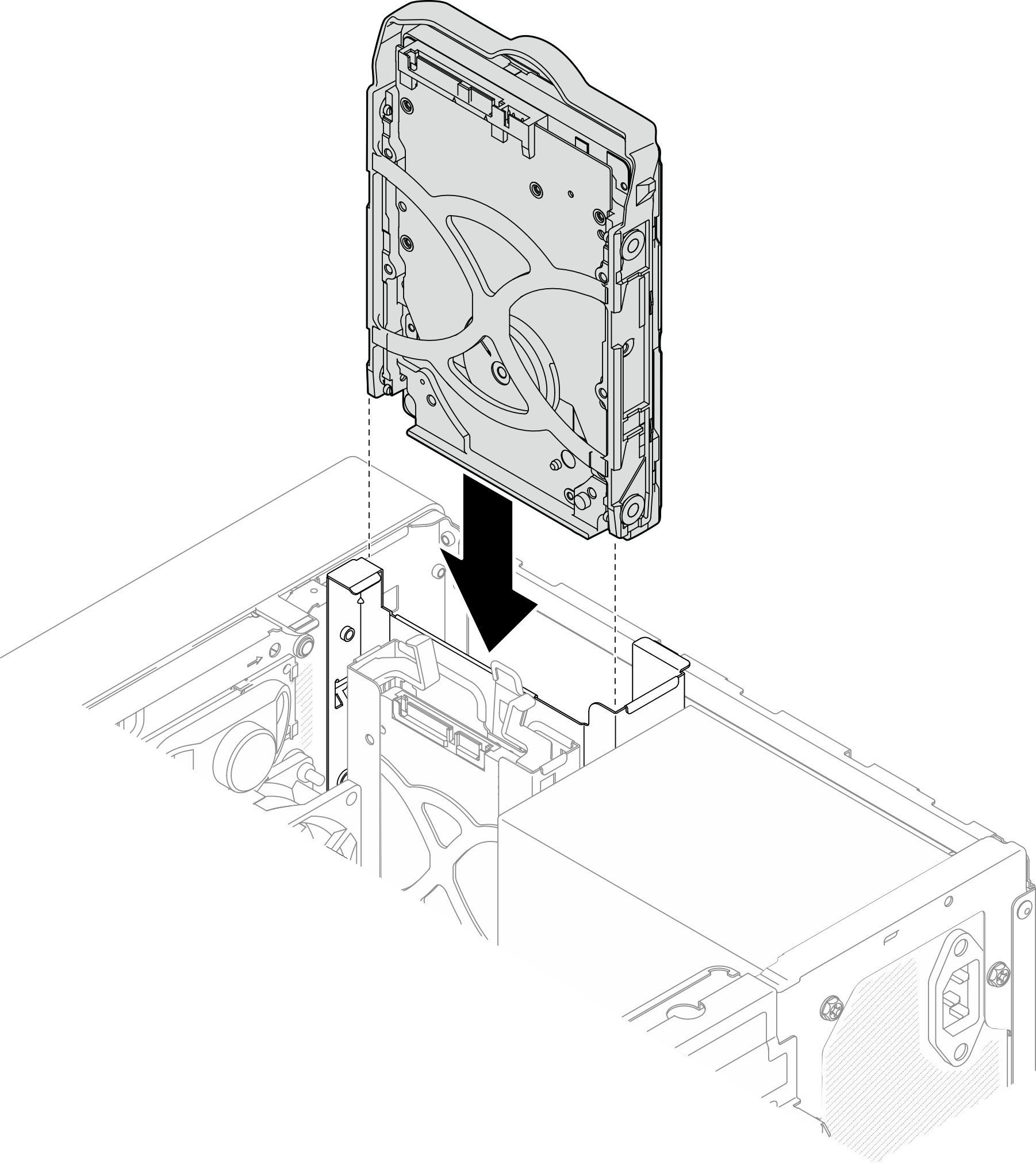
NoteDepending on the configuration, the 3.5-inch drive may be the model in the illustration below.
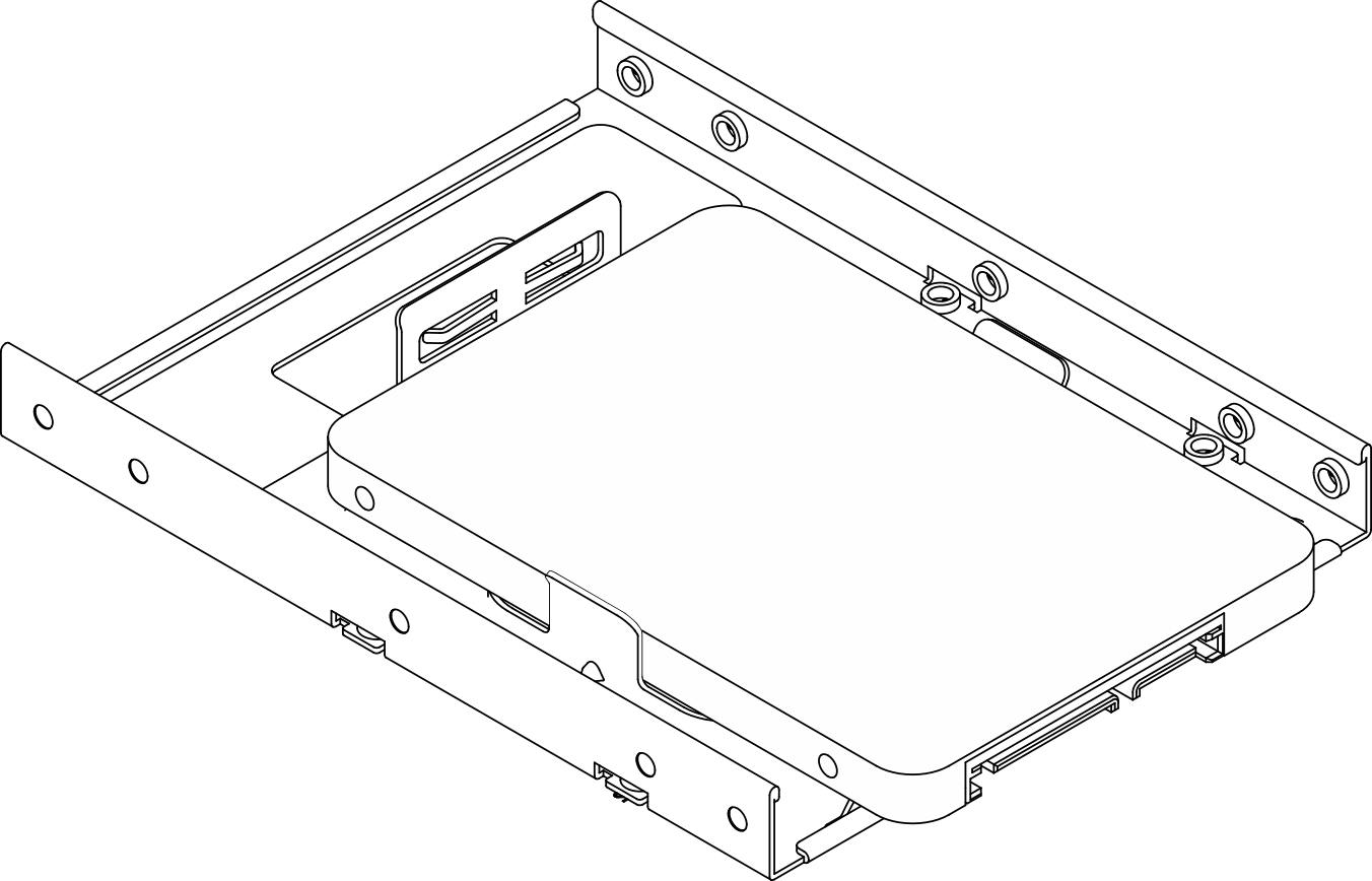 Install a 2.5-inch drive into the retainerFigure 3. Installing a 2.5-inch drive into the retainer
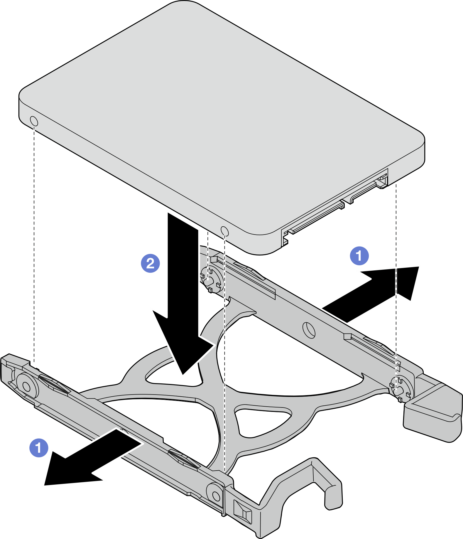
- Face the retainer handles upward and push the drive assembly into the drive bay. Press the drive assembly firmly to ensure it is seated correctly.Install 3.5-inch drive assembly into drive bay 1Figure 4. Install 3.5-inch drive assembly into drive bay 1
 Install 2.5-inch drive assembly into drive bay 2Figure 5. Install 2.5-inch drive assembly into drive bay 2
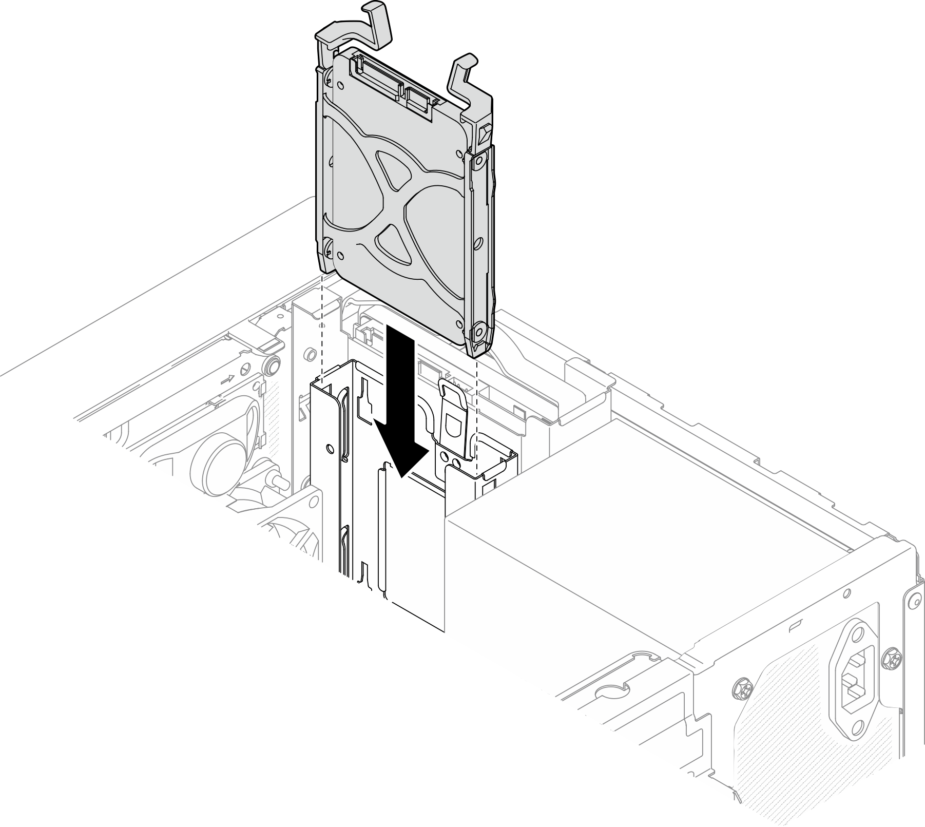
Complete the parts replacement, see Complete the parts replacement.
Check the drive activity LED on the front panel to verify if the drives are operating correctly.
Table 1. Drive activity LED behavior Status Color Description Solid on White The drives are active. Off None The drives are not active. Use the Lenovo XClarity Provisioning Manager Lite to configure the RAID if necessary. For more information, see RAID Setup.