Install an optical drive or a tape drive
Follow this procedure to install an optical drive or a tape drive.
Note
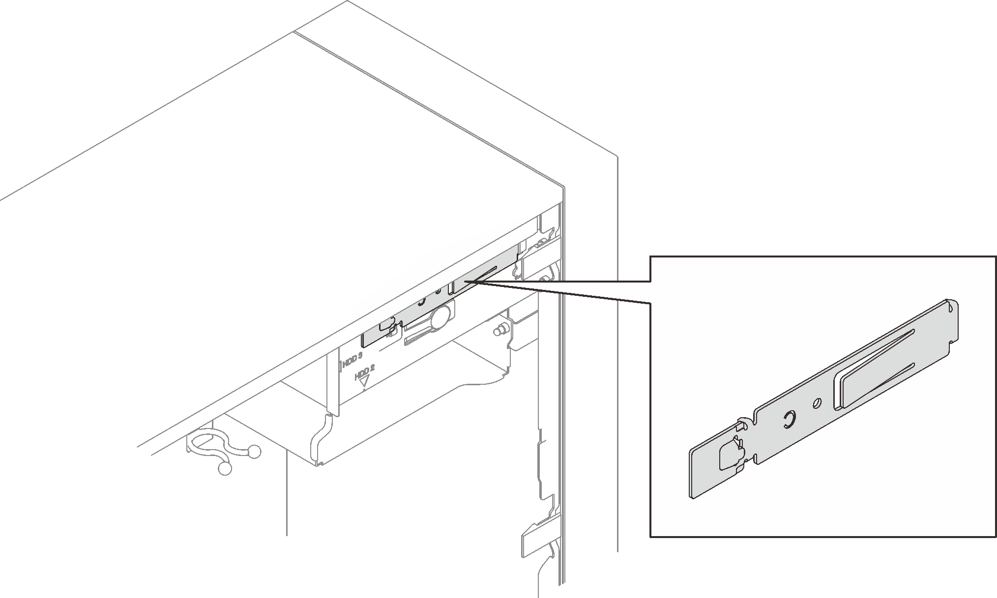
The retainer required for this procedure is stored on the side of the chassis, see the illustration below for its location. If the retainer is not available, contact Lenovo Support for the miscellaneous kit that includes the retainer.


S002
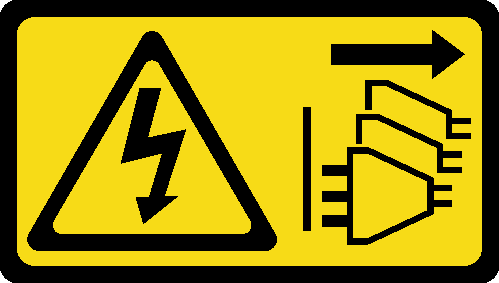
CAUTION
The power-control button on the device and the power switch on the power supply do not turn off the electrical current supplied to the device. The device also might have more than one power cord. To remove all electrical current from the device, ensure that all power cords are disconnected from the power source.
S006

CAUTION
When laser products (such as CD-ROMs, DVD drives, fiber optic devices, or transmitters) are installed, note the following:
- Do not remove the covers. Removing the covers of the laser product could result in exposure to hazardous laser radiation. There are no serviceable parts inside the device.
- Use of controls or adjustments or performance of procedures other than those specified herein might result in hazardous radiation exposure.
S007
CAUTION
This product contains a Class 1M laser. Do not view directly with optical instruments.
S008
DANGER
danger
Some laser products contain an embedded Class 3A or Class 3B laser diode. Note the following:
Laser radiation when open. Do not stare into the beam, do not view directly with optical instruments, and avoid direct exposure to the beam.
To install an optical or tape drive, complete the following steps:
- Align the retainer on the side of the optical or tape drive and install it.Figure 1. Installing the drive retainer to an optical drive
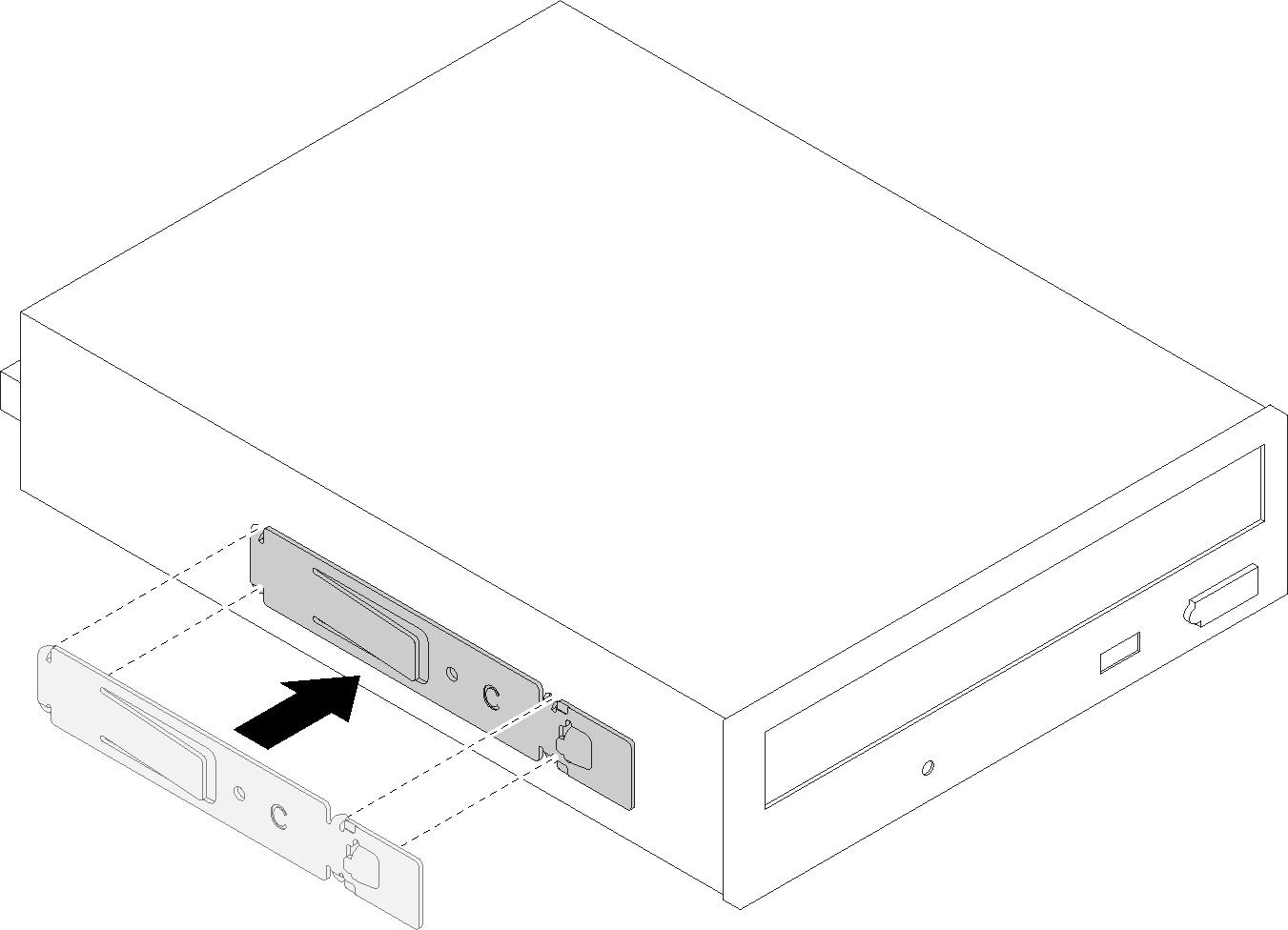 Figure 2. Installing the drive retainer to a tape drive
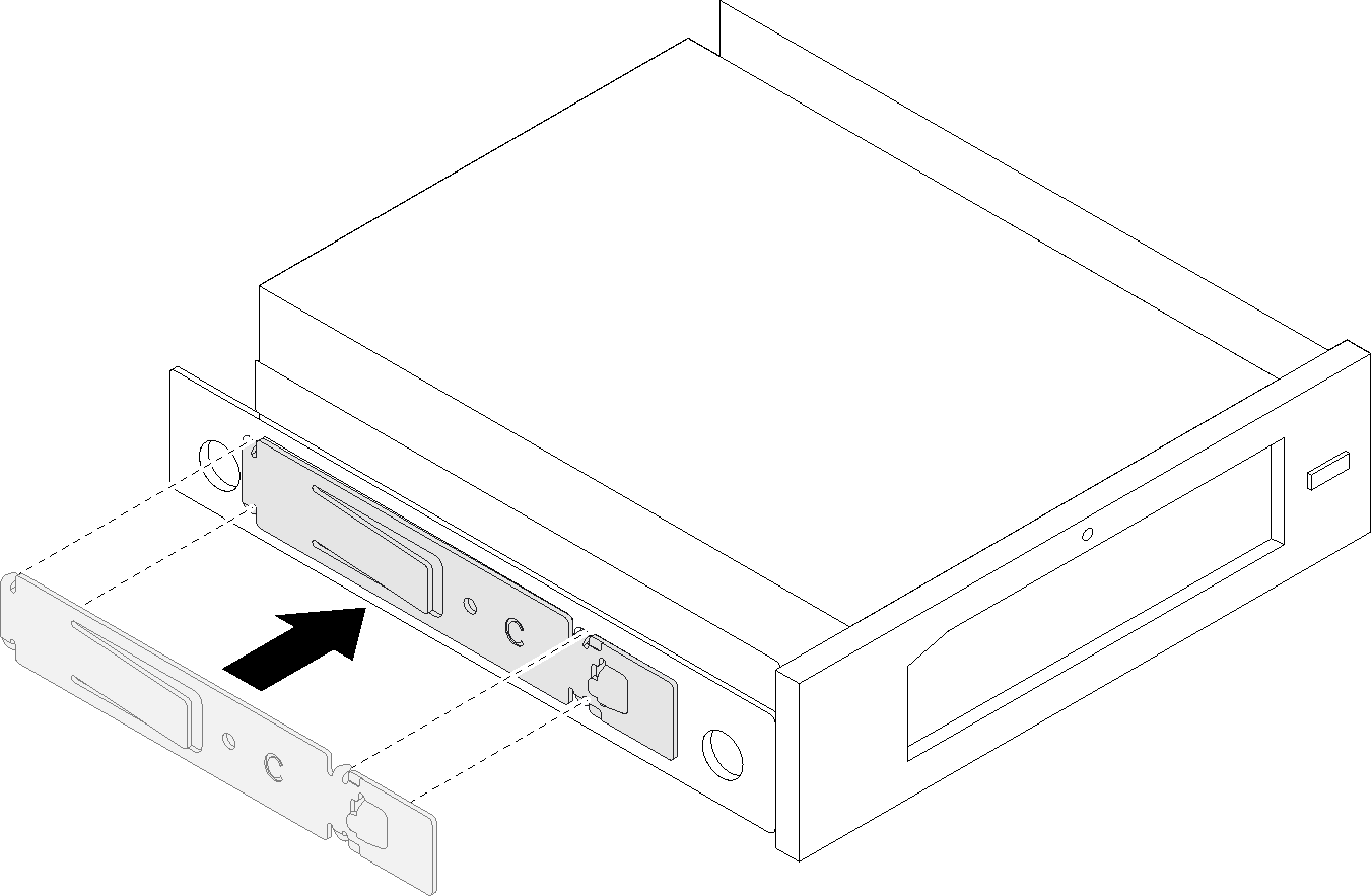
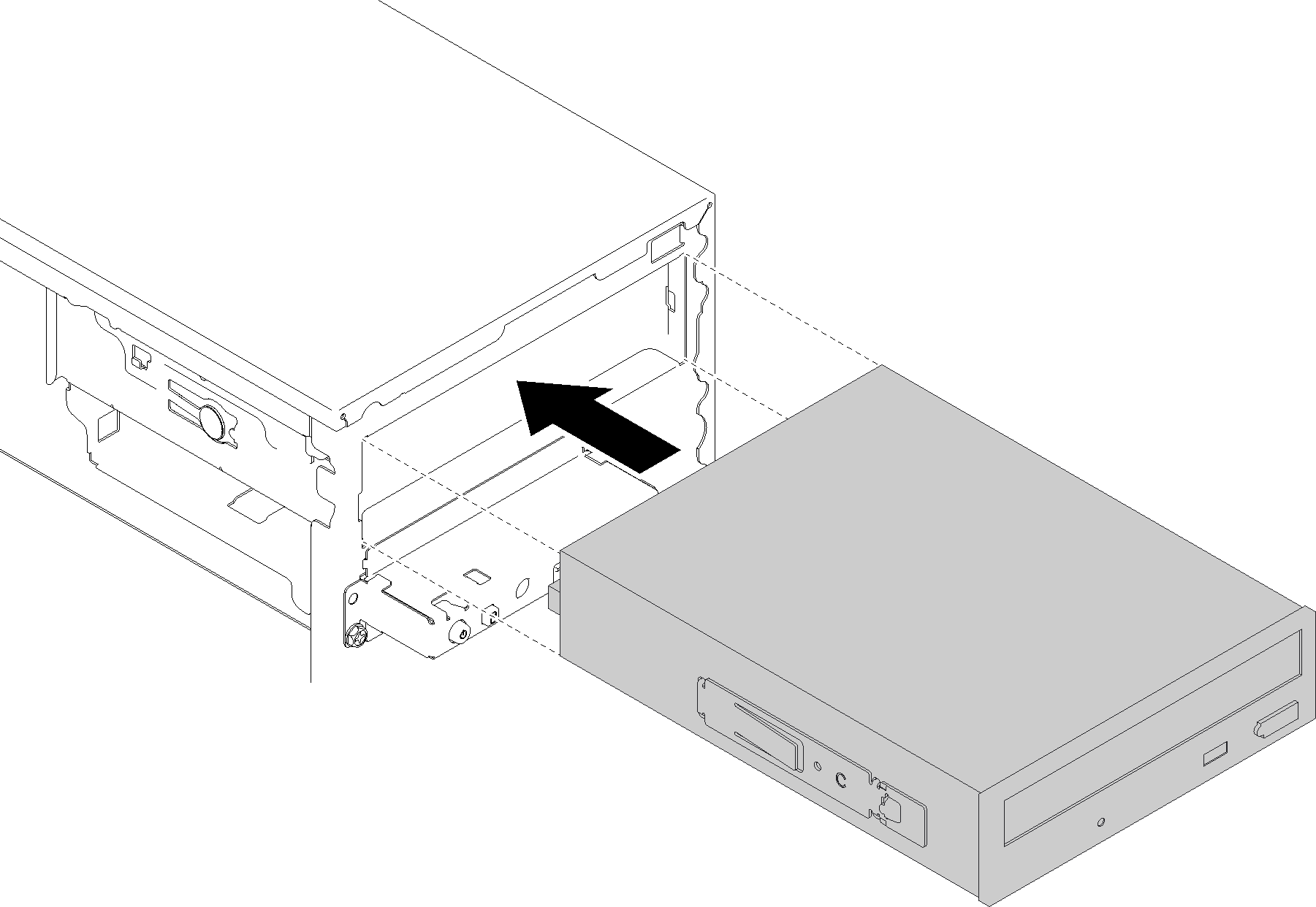
- Align the optical or tape drive to the drive bay, and slide it in until it snaps into place.Figure 3. Installing the optical drive assembly
Demo video
Give documentation feedback