Install a 5.25-inch drive bay adapter assembly
Follow this procedure to install an optical drive or a tape drive.


S002

CAUTION
The power-control button on the device and the power switch on the power supply do not turn off the electrical current supplied to the device. The device also might have more than one power cord. To remove all electrical current from the device, ensure that all power cords are disconnected from the power source.
S006

CAUTION
When laser products (such as CD-ROMs, DVD drives, fiber optic devices, or transmitters) are installed, note the following:
- Do not remove the covers. Removing the covers of the laser product could result in exposure to hazardous laser radiation. There are no serviceable parts inside the device.
- Use of controls or adjustments or performance of procedures other than those specified herein might result in hazardous radiation exposure.
S007
CAUTION
This product contains a Class 1M laser. Do not view directly with optical instruments.
S008
DANGER
danger
Some laser products contain an embedded Class 3A or Class 3B laser diode. Note the following:
Laser radiation when open. Do not stare into the beam, do not view directly with optical instruments, and avoid direct exposure to the beam.
To install a 5.25-inch drive bay adapter assembly, complete the following steps:
- Install the components into the drive bay adapter if necessary:
Slim optical drive
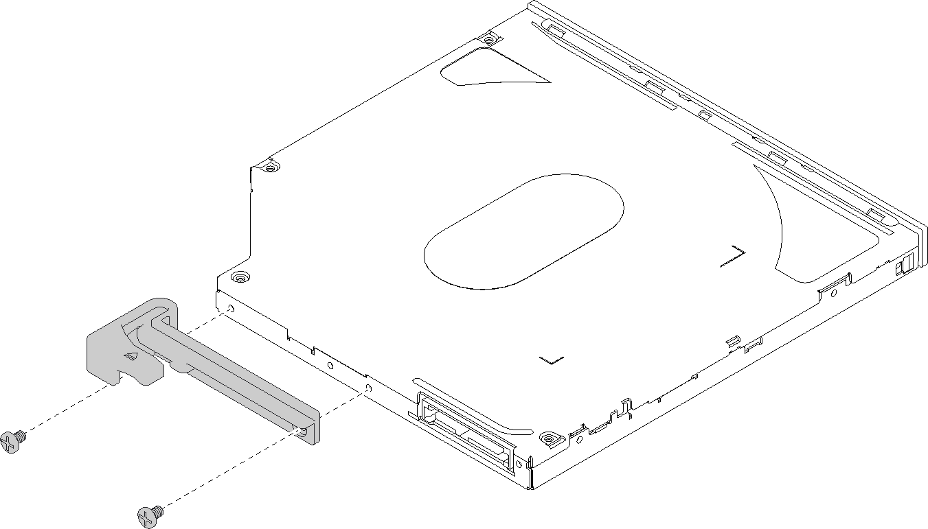
- Align the screw holes on the retainer to the corresponding ones one the slim optical drive, and secure the retainer with two screws.Figure 1. Installing the retainer to the slim optical drive
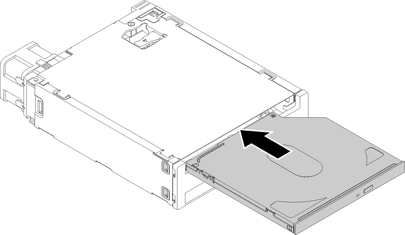
- Slide the slim optical drive into the slot on the front of the drive adapter until it snaps into place.Figure 2. Installing the slim optical drive into the drive bay adapter
Simple-swap drive
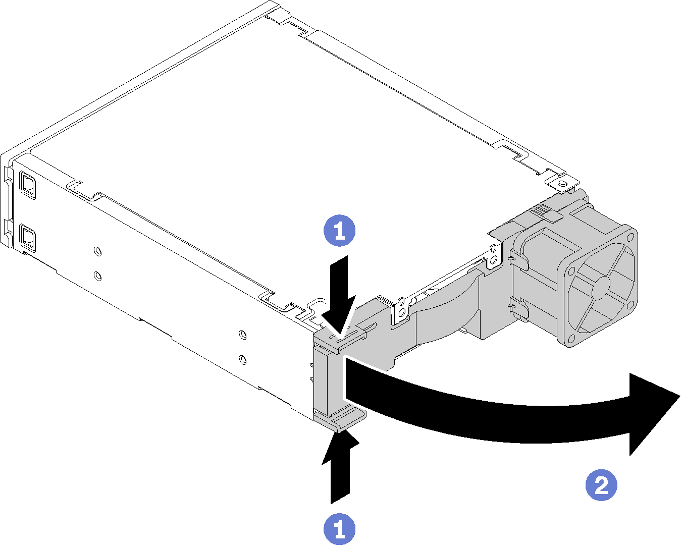
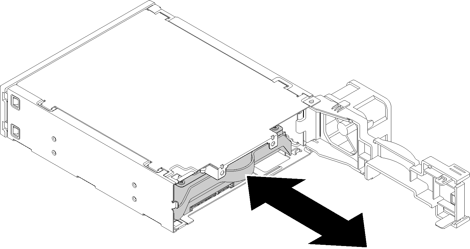
- Pinch the release tab on the rear of the drive assembly as illustrated; then, pivot the latch to the open position.Figure 3. Opening the latch of the adapter assembly
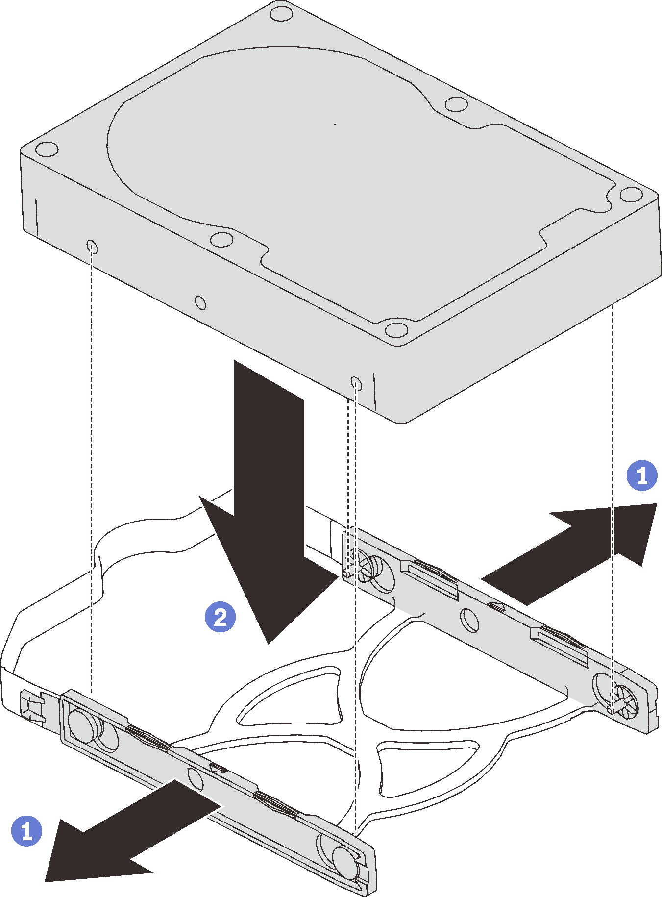
- Align the four holes on the drive with the corresponding pins on the retainer, and lower the drive until it is secured in the retainer.Figure 4. Installing a 3.5-inch drive into the retainer
- Slide the drive assembly into the drive adapter.Figure 5. Installing the drive assembly into the drive adapter
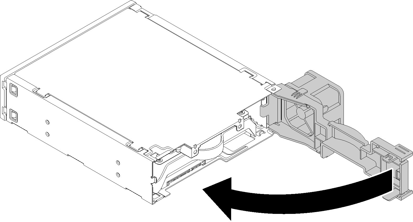
- Close the drive adapter latch.Figure 6. Closing the drive adapter latch
- Align the screw holes on the retainer to the corresponding ones one the slim optical drive, and secure the retainer with two screws.
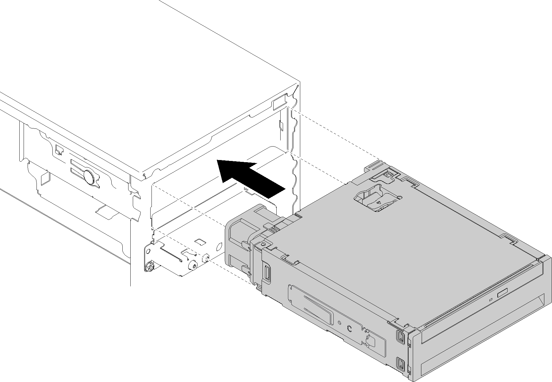
- Slide the drive bay adapter assembly slide into drive 3 until it clicks into place.Figure 7. Installing the drive bay adapter assembly
Demo video
Give documentation feedback