Side view
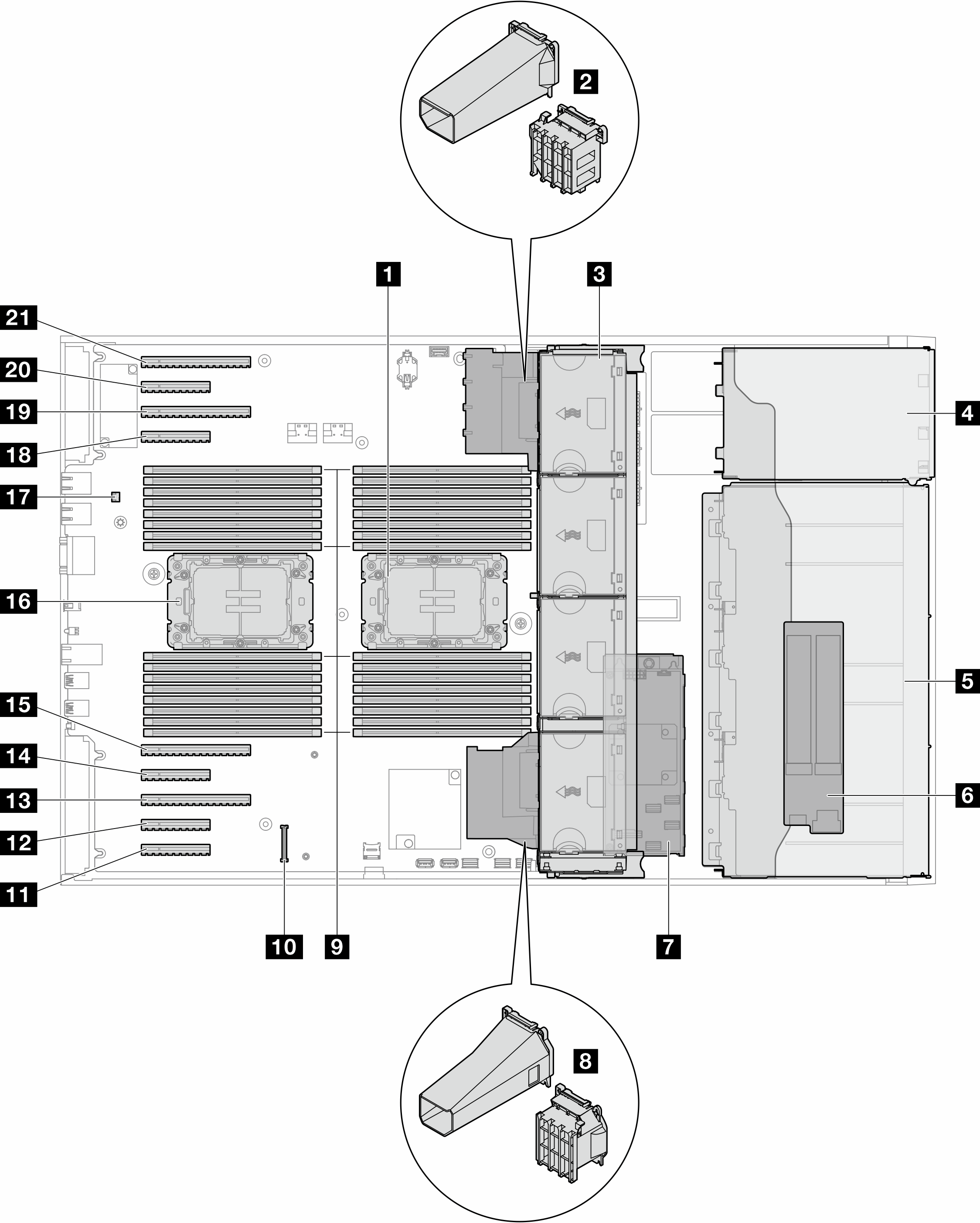
Follow the instructions in this section to locate the components from the side of the server.
Figure 1. Side view of the ST650 V3


| 1 Processor 2 and heat sink | 12 PCIe slot 8 | ||
| 2 PCIe adapter holder or A2/L4 GPU air duct, upper1 | 13 PCIe slot 7 | ||
| 3 Fan 4, fan 3, fan 2, fan 1 (top to bottom) | 14 PCIe slot 6 | ||
| 4 Drive bay for ODD drive cage, tape drive cage, or expansion drive cage | 15 PCIe slot 5 | ||
| 5 3.5-inch or 2.5-inch drive cages1 | 16 Processor 1 and heat sink | ||
| 6 M.2 adapter | 17 Intrusion switch | ||
| 7 Internal CFF RAID | 18 PCIe slot 4 | ||
| 8 PCIe adapter holder or A2/L4 GPU air duct, lower1 | 19 PCIe slot 3 | ||
| 9 Memory module slots | 20 PCIe slot 2 | ||
| 10 Firmware and RoT security module connector | 21 PCIe slot 1 | ||
| 11 PCIe slot 9 |
Note
1 The illustration shows the location of certain parts. Some parts may not be supported at the same time within certain configuration(s).
Give documentation feedback