Rear view
The rear of the server provides access to several components, including the power supplies, PCIe adapters, serial port, and Ethernet port.
Components on the rear view
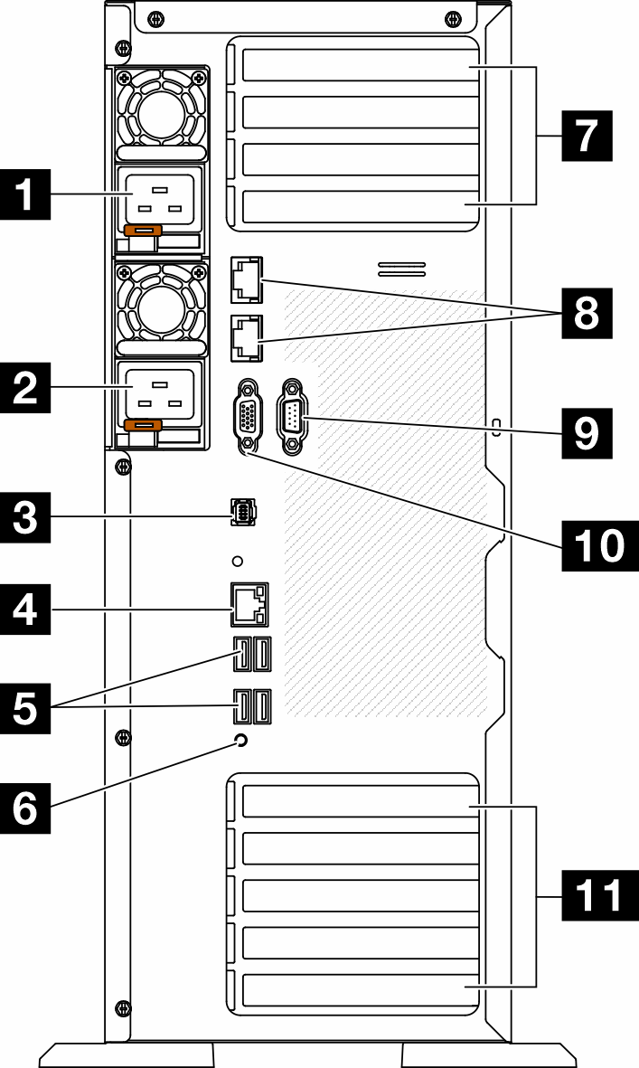
| 1 Power supply unit 1 | 7 PCIe slots 1-4 (top to bottom) |
| 2 Power supply unit 2 (optional) | 8 10GbE connectors (2) |
| 3 External Diagnostics Handset connector | 9 Serial-port-module slot |
| 4 XClarity Controller network connector | 10 VGA connector |
| 5 Four USB 3.1 Gen 1 connectors (4) | 11 PCIe slots 5-9 (top to bottom) |
| 6 NMI button |
Listed in this section are the components that can be seen in the rear view. For detailed information about the LEDs for these components, see Rear system LEDs.
1 2 Power supply units
750-watt Platinum
1100-watt Platinum
1100-watt Titanium
1800-watt Platinum
1800-watt Titanium
2600-watt Titanium
Note100V+ is only allowed on the following:
750-watt Platinum
1100-watt Platinum
200V+ is allowed only with the following power supplies:
750-watt Platinum
1100-watt Platinum
1100-watt Titanium
1800-watt Platinum
1800-watt Titanium
2600-watt Titanium
On each power supply, there are three status LEDs near the power cord connector. For more details, see Power supply LEDs.
3 External Diagnostics Handset connector
Connect the External Diagnostics Handset here. For more details, see External Diagnostics Handset.
4 XClarity Controller network connector
Used to attach an Ethernet cable to manage the system using XClarity Controller. For more details, see XCC system management port (10/100/1000 Mbps RJ-45) LEDs.
5 USB 3.1 Gen 1 connectors
Used to attach a device that requires a USB 2.0 or 3.2 Gen 1 connection, such as a keyboard, a mouse, or a USB flash drive.
6 NMI button
Press this button to force a non-maskable interrupt (NMI) to the processor. You might have to use a pen or the end of a straightened paper clip to press the button. You can also use it to force a blue-screen memory dump. Use this button only when you are directed to do so by Lenovo Support.
7 PCIe slots 1-4 (top to bottom)
Install PCIe adapters into these slots.
8 10GbE connector
This connector is used to attach a 10Gb Ethernet cable. Each 10GbE connector has two status LEDs to help identify the Ethernet connectivity and activity. For more information, see Rear system LEDs.
9 Serial-port-module slot
Connect a 9-pin serial device to this connector. The serial port is shared with the XCC. The XCC can take control of the shared serial port to redirect serial traffic, using Serial over LAN (SOL).
10 VGA connector
Used to attach a VGA-compatible video device, such as a VGA monitor.
11 PCIe slots 5-9 (top to bottom)
Install PCIe adapters into these slots.