Front view
This section contains information about the controls, LEDs, and connectors on the front of the server.
These different models have the same front I/O module. The connectors on this front I/O module are shown below. For the front operator panel LEDs on the front I/O module, see Front operator panel LEDs.
Connectors on the front I/O module
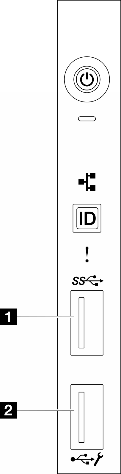
| 1 Front USB 3.1 Gen 1 connector | 2 USB 2.0 connector with Lenovo XClarity Controller management |
Server models with twelve 3.5-inch drive bays
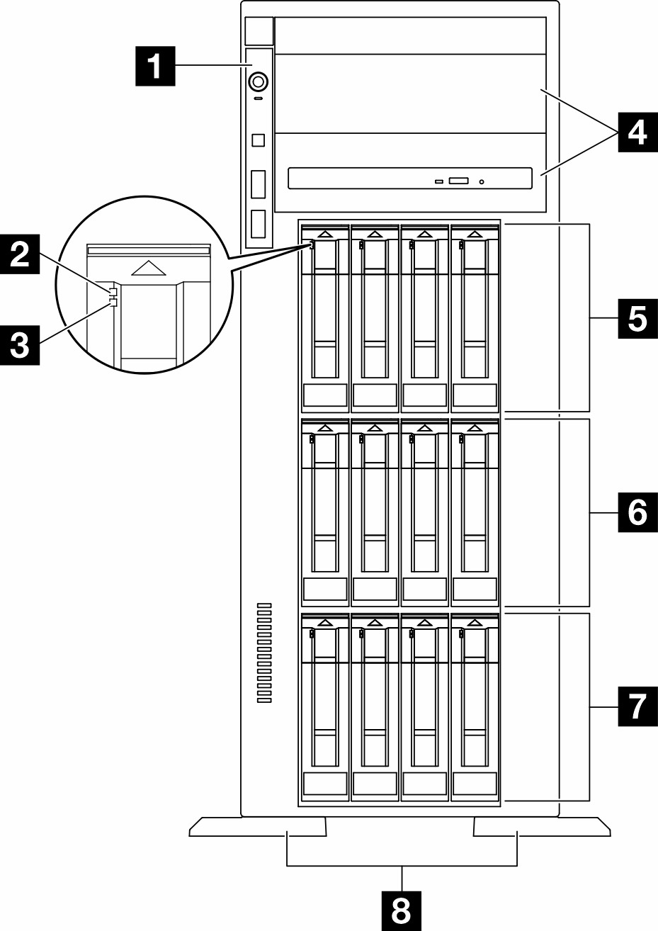
| 1 Front I/O module | 5 3.5-inch drive bays 8-11 |
| 2 Drive activity LED (green) | 6 3.5-inch drive bays 4-7 |
| 3 Drive status LED (yellow) | 7 3.5-inch drive bays 0-3 |
| 4 Optical-drive bays 1-2 | 8 Foot stands |
1 Front I/O module
For information about the front operator panel LEDs on this front I/O module, see Front operator panel LEDs.
2 3 Drive activity LED (green) and Drive status LED (yellow)
For information about Drive LEDs, see Drive LEDs.
4 Optical-drive bays 1-2
Depending on the model, the server might come with an optical drive installed in the lower 5.25-inch optical-drive bay. The upper 5.25-inch optical-drive bay is for a secondary optical drive or a tape drive. Some models have a secondary optical drive or a tape drive installed.
5 6 7 3.5-inch drive bays
The drive bays are used to install 3.5-inch drives. When you install drives, follow the order of the drive bay numbers. The EMI integrity and cooling of the server are protected by having all drive bays occupied. The vacant drive bays must be occupied by drive bay fillers or drive fillers.
8 Foot stands
For tower form factor models, the foot stands help the server stand steadily.
Server models with sixteen 3.5-inch drive bays
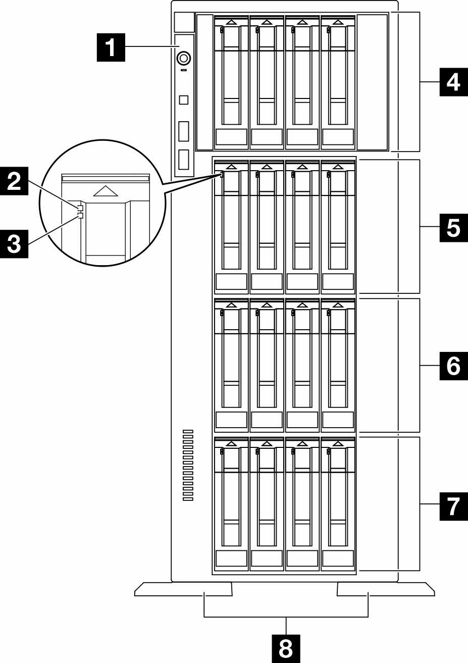
| 1 Front I/O module | 5 3.5-inch drive bays 8-11 |
| 2 Drive activity LED (green) | 6 3.5-inch drive bays 4-7 |
| 3 Drive status LED (yellow) | 7 3.5-inch drive bays 0-3 |
| 4 3.5-inch drive bays 12-15 | 8 Foot stands |
1 Front I/O module
For information about the front operator panel LEDs on this front I/O module, see Front operator panel LEDs.
2 3 Drive activity LED (green) and Drive status LED (yellow)
For information about Drive LEDs, see Drive LEDs.
4 5 6 7 3.5-inch drive bays
The drive bays are used to install 3.5-inch drives. When you install drives, follow the order of the drive bay numbers. The EMI integrity and cooling of the server are protected by having all drive bays occupied. The vacant drive bays must be occupied by drive bay fillers or drive fillers.
8 Foot stands
For tower form factor models, the foot stands help the server stand steadily.
Server models with thirty-two 2.5-inch drive bays
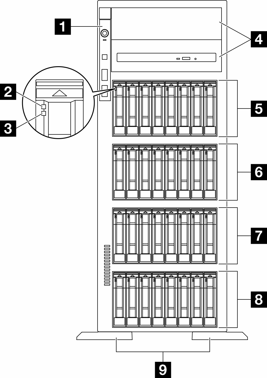
| 1 Front I/O module | 6 2.5-inch dive bays 16-23 |
| 2 Drive activity LED (green) | 7 2.5-inch drive bays 8-15 |
| 3 Drive status LED (yellow) | 8 2.5-inch drive bays 0-7 |
| 4 Optical-drive bays 1-2 | 9 Foot stands |
| 5 2.5-inch drive bays 24-31 |
1 Front I/O module
For information about the front operator panel LEDs on this front I/O module, see Front operator panel LEDs.
2 3 Drive activity LED (green) and Drive status LED (yellow)
For information about Drive LEDs, see Drive LEDs.
4 Optical-drive bays 1-2
Depending on the model, the server might come with an optical drive installed in the lower 5.25-inch optical-drive bay. The upper 5.25-inch optical-drive bay is for a secondary optical drive or a tape drive. Some models have a secondary optical drive or a tape drive installed.
5 6 7 8 2.5-inch drive bays
The drive bays are used to install 2.5-inch drives. When you install drives, follow the order of the drive bay numbers. The EMI integrity and cooling of the server are protected by having all drive bays occupied. The vacant drive bays must be occupied by drive bay fillers or drive fillers.
9 Foot stands
For tower form factor models, the foot stands help the server stand steadily.