Install the management switch (optional)
This section covers the procedures to install theThinkSystem NE0152T RackSwitch as the management switch in a ThinkAgile CP solution.
A dedicated out-of-band (OOB) management switch is required for this solution. If the Lenovo ThinkSystem NE0152T RackSwitch is not used, you must provide an OOB management switch with the correct configuration. Disregard this procedure if you are not including the NE0152T as the management switch in your solution.
This section describes how to install the NE0152T switch in a standard 19–inch equipment rack using the mounting kit included with the switch.
The following parts are included in the standard mounting kit:
| Item number | Description | Quantity |
1 | Mounting brackets | 2 |
2 | M4 screws | 8 |
3 | M6 screws | 4 |
4 | M6 clip nuts | 4 |
5 | M6 cage nuts | 4 |
6 | M6 locking washers | 4 |
The rack-mounting frame may be unable to support the weight of the switch with only the front post mounting brackets (2-post application). If the switch has an undesirable amount of sag, it is recommended to use a 4-post mounting kit.
For earthquake stability, mount the switch in a 4-post rack.
If you are using a non-Lenovo switch as the management switch, keep 1U of empty space between the interconnect switches and the management switch so that power or network cables can use this space.
Statement 26

Do not place any object on top of rack‐mounted devices.
To install the ThinkSystem NE0152T RackSwitch in a standard equipment rack, complete the following steps:
- Attach a mounting bracket (item 1 in the illustration) to each side of the switch with M4 screws (item 2). Torque the screws to approximately 2.0 newton‐meters (Nm) ± 0.1 Nm (17.7 inch‐pounds).Figure 1. Attaching mounting brackets to switch
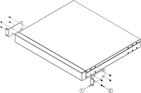
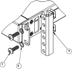
- Secure the switch unit to the rack posts with M6 screws (item 3 in illustration), washers (item 6), and either clip nuts (item 4) or cage nuts (item 5). Torque the screws to approximately 5.7 Nm ± 0.1 Nm (50 inch‐pounds).Figure 2. Securing switch to rack posts
- If not using the 1U air‐duct option, install the power cord retention clip.Note
The power cord retention clip is not used when the 1U air‐duct option is installed.
Figure 3. Installing power cord retention clip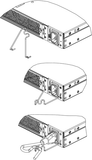
The installation of the management switch is now complete.