Installing the microprocessor 2 expansion board
Use this information to install the microprocessor 2 expansion board into the server.
To install the microprocessor 2 expansion board, complete the following steps:
Note
While installing 16 GB 1.5 Volt/ 32 GB 1.35 Volt, please refers to the table of fan configuration instruction.
| Fans | Conditions |
|---|---|
| 2 and Rear fan | Standard for all systems |
| 3 |
|
| 1 | Optional redundant fan (P/N: 00D2593) Attention When fan 3 is installed and 16 GB 1.5V / 32 GB 1.35V DIMMs are installed, fan 1 must also be populated. |
- Read the safety information that begins in Safety and Installation guidelines.
- Turn off the server (see Turning off the server) and all attached peripheral devices. Disconnect all power cords; then, disconnect all external cables from the server.
- Carefully turn the server on its side so that it is lying flat, with the cover facing up.AttentionDo not allow the server to fall over.
- Unlock and remove the left-side cover (see Removing the left-side cover)
- Remove the air baffle (see Removing the air baffle)
- Remove the fan assembly (see Removing the fan assembly)
- Touch the static-protective package that contains the microprocessor 2 expansion board to any unpainted metal surface on the server; then, remove the microprocessor 2 expansion board from the package.
- Install the microprocessor 2 expansion board side bracket.
- Align the side bracket with the holes on the chassis and install the side bracket on the system board.
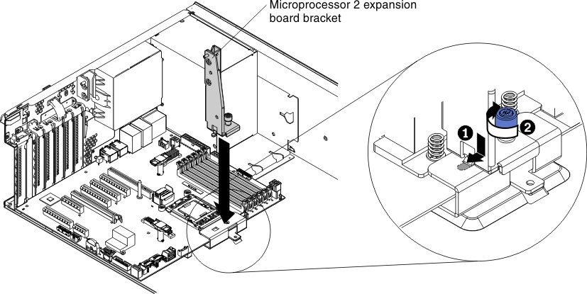
- Fasten the thumbscrew on the side bracket.
- Align the side bracket with the holes on the chassis and install the side bracket on the system board.
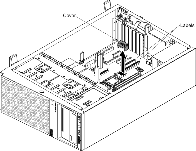
- Remove the cover on the microprocessor 2 expansion board connector and labels of CPU slot and PCI slot 1 on the system board.
- Make sure the microprocessor 2 expansion board release levers are in the open position.
- Align the holes on the microprocessor 2 expansion board to the guide pins on the system board. Install the microprocessor 2 expansion board on the system board.
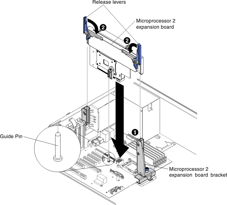
- Press the microprocessor 2 expansion board firmly and vertically to the system board.Note
- Static electricity that is released to internal server components when the server is powered-on might cause the server to halt, which might result in the loss of data. To avoid this potential problem, always use an electrostatic-discharge wrist strap or other grounding system when you work inside the server with the power on.
- Make sure that none of the server cables are caught under the microprocessor 2 expansion board.
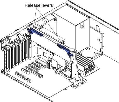
- Rotate the release lever to the close position to secure the microprocessor 2 expansion board in place.NotePress the microprocessor 2 expansion board connector to make sure the connector is seated securely on the system board.
- Connect the microprocessor 2 power cable (P4) to its connector on the system board (seePower Cable Connection ).
If you have other devices to install or remove, do so now. Otherwise, go to Completing the installation.
Give documentation feedback