Removing the system board
Use this information to remove the system board.
Before you remove the system board from the server, take the following steps to save data, firmware, and configuration data:
- Record all system configuration information, such as IMM IP addresses, vital product data, and the machine type, model number, serial number, Universally Unique Identifier, and asset tag of the server.
- Using the Advanced Settings Utility (ASU), save the system configuration to external media.
- Save the system-event log to external media.
Note
- When you replace the system board, you must either update the server with the latest firmware or restore the pre-existing firmware that the customer provides on a diskette or CD image. Make sure that you have the latest firmware or a copy of the pre-existing firmware before you proceed.
- Before you replace the system board, make sure that you backup any features on demand (FoD) keys that were enabled. Remember to re-enable the features on demand (FoD) keys after installing the new system board. For more information on Features on Demand (FoD), including instructions for automating the activation and installation of the activation key by using ToolsCenter or Systems Director, see the Lenovo Features on Demand User’s Guide at the Lenovo Features on Demand website under the Help section.
To remove the system board, complete the following steps:
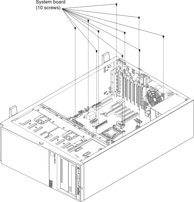
- Loosen 10 screws from the system board showed as the illustration, and keep they in a safe place for future use.
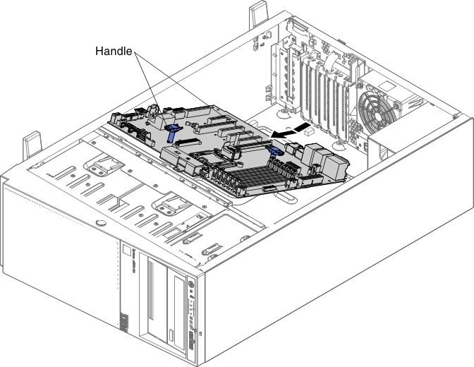
- Grasp the handle of the system board. Then, carefully move the system board backward and lift it up to be removed from the chassis.
Give documentation feedback