Installing components
After you install the Flex System Enterprise Chassis in a rack, install all of the components in the chassis.
- Read Safety and Installation guidelines.
- Make sure that the Chassis Management Module firmware is the latest level available. See Updating the CMM firmware for more information.
Compute nodes
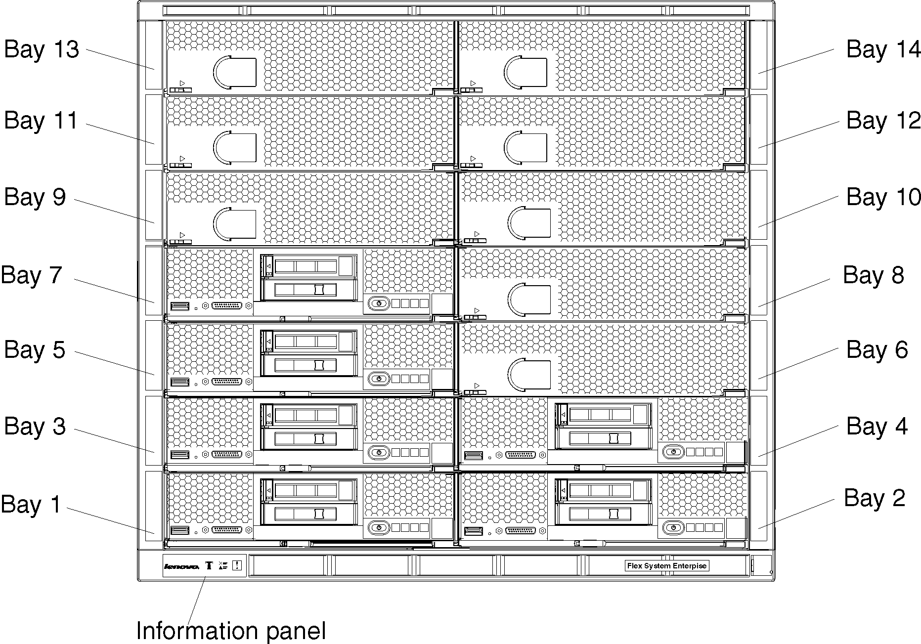
The following illustration shows the locations of node bays in the Flex System Enterprise Chassis.
- A 1-bay compute node occupies one node bay in the chassis.
- A 1-bay compute node with captive-mode expansion node occupies two adjacent node bays (horizontally) in the chassis and requires the chassis shelf to be removed prior to installation.
- A 2-bay compute node occupies two adjacent node bays (horizontally) in the chassis and requires the chassis shelf to be removed prior to installation.
- A 4-bay storage node or storage expansion enclosure occupies four adjacent node bays (two vertically and horizontally) in the chassis and requires the chassis shelves and shelf supports to be removed prior to installation.
Power supplies
The chassis power load is dependent on the number and type of compute nodes, storage nodes, I/O modules, and management modules that are installed in the chassis. The number and type of power supplies that you install determines how much power is available to power all of these devices. The amount of power available must be sufficient for the expected chassis load.
You can use the Lenovo Capacity Planner to determine the power load for a specific chassis configuration. See Lenovo Capacity Planner for more information.
- Up to six power supplies can be installed.
- Do not mix different types of power supplies in the Flex System Enterprise Chassis.
- Each chassis must contain either all ac-powered supplies or all dc-powered supplies.
- For ac-powered chassis, do not mix 2100 W and 2500 W power supplies. Chassis powered by ac power should contain only power supplies of the same wattage.
- Install power supplies from the bottom up starting with power bays 1 and 4, then power bays 2 and 5, then power bays 3 and 6.
Install power supplies according to the number of populated node bays as shown in Table 1. See also Power supplies for more information.
| Number of populated node bays | Power supplies required |
|---|---|
| 1 - 4 | 2 |
| 5 - 6 | 3 |
| 7 - 8 | 4 |
| 9 - 11 | 5 |
| 12 - 14 | 6 |
80 mm fan modules
The number of 80 mm fans that you install depends on the number of populated node bays. Up to eight 80 mm fan modules can be installed.
Install 80 mm fan modules according to the number of populated node bays as shown in Table 2. See also Fan modules for more information.
| Fan zone 1 (behind node bays 1, 3, 5, 7, 9, 11, and 13) | Fan zone 2 (behind node bays 2, 4, 6, 8, 10, 12, and 14) | ||
|---|---|---|---|
| Number of populated node bays | 80 mm fans required | Number of populated node bays | 80 mm fans required |
| 1 - 2 | 2 | 1 - 2 | 2 |
| 3 - 4 | 3 | 3 - 4 | 3 |
| 5 - 7 | 4 | 5 - 7 | 4 |