Rear Door Heat eXchanger V2
See this topic to learn about parts of ThinkSystem Rear Door Heat eXchanger V2.
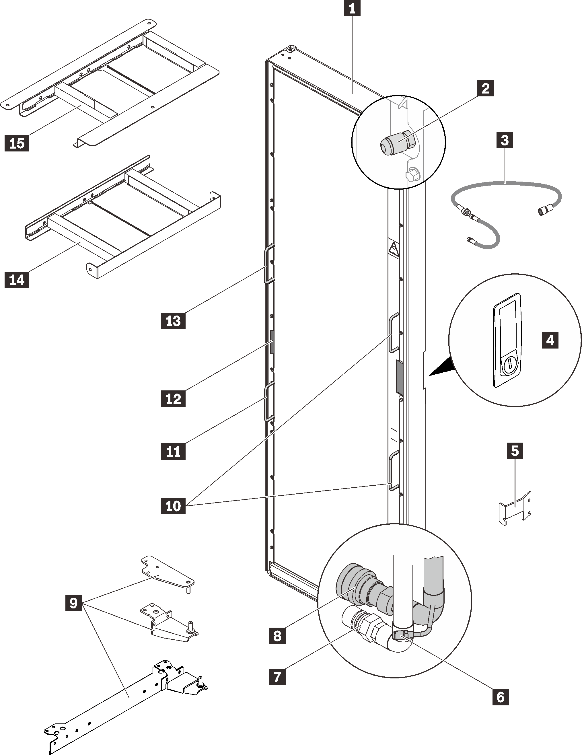
| 1 Rear Door Heat eXchanger assembly | 9 Hinge kit |
| 2 Air-purging valve | 10 Lift handles |
| 3 Air-purging tool | 11 Lift handle |
| 4 Door latch | 12 Serial number |
| 5 Latch plate | 13 Lift handle |
| 6 Drain valve | 14 Lower air baffle |
| 7 Return manifold coupling | 15 Upper air baffle |
| 8 Supply manifold coupling |
Rear Door Heat eXchanger V2 specifications
| Dimension |
|
| Weight | Empty: 39 kg / 121 lbs |
| Air movement | Provided by servers and other devices in the rack |
| Air temperature drop | With high-heat-load devices, up to 25°C (45°F) between the air exiting the rack devices and the air exiting the heat exchanger. |
| Water |
|
For setup and installation, see Set up Rear Door Heat eXchanger V2.
Heat exchanger performance
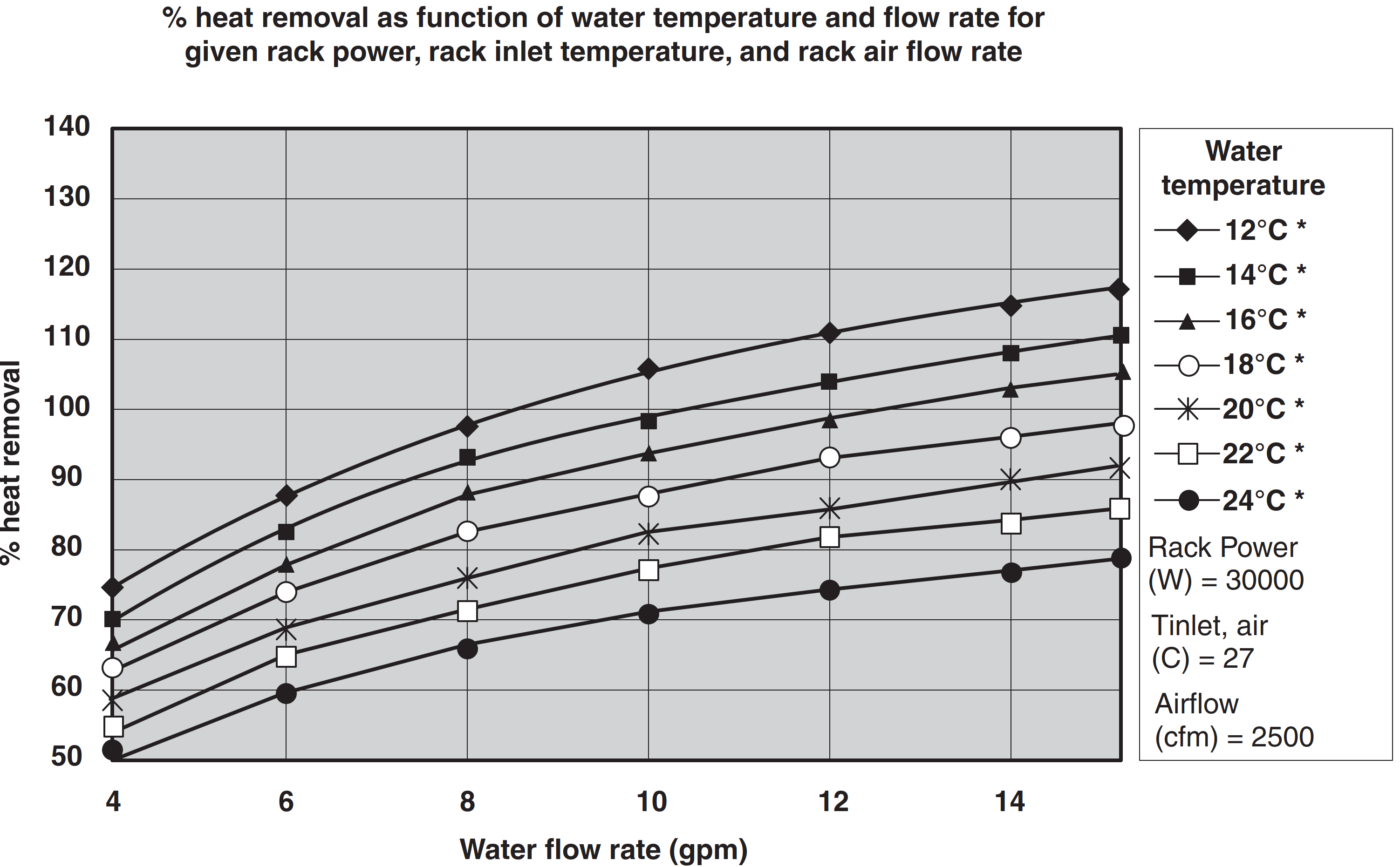
Expected performance of the heat exchanger is illustrated in the following figure for a typical inlet air temperature of 27°C (80.6°F), with a fully populated rack, near uniform power dissipation, and a 30-40 kW heat load. By selecting the correct water inlet temperature and water flow rate, you can achieve the necessary heat removal. A heat removal of 100% indicates that an amount of heat equivalent to that generated by the devices has been removed by the heat exchanger and the average air temperature leaving the heat exchanger is identical to that entering the rack (27°C /80.6°F in this example). Heat removal in excess of 100% indicates that the heat exchanger not only removed all of the heat generated by the devices but further cooled the air so that the average air temperature leaving the rack is actually lower than that entering the rack.
As described in Water specifications for the secondary cooling loop, a given water temperature may be used only if the system that is supplying the water is able to measure the room dew point and automatically adjust the water temperature accordingly. Otherwise, the water temperature must be above the maximum dew point that is allowed at that data center installation.
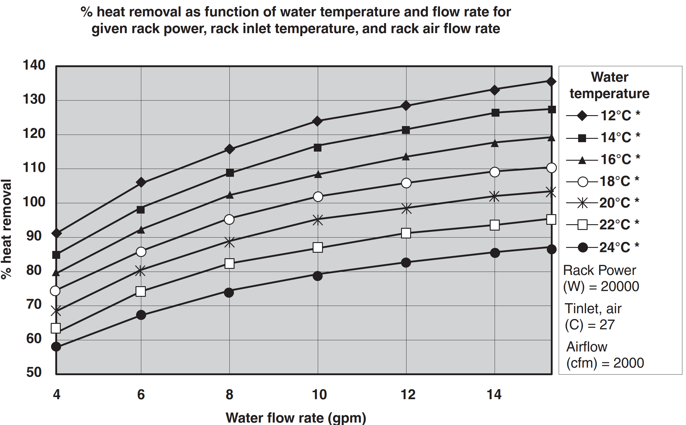
Performance data is shown in the following figure for a 20 kW heat load. Because of the lower heat load, a specific level of cooling can be achieved with warmer water, a lower flow rate, or both.