Memory module installation rules and order
Memory modules must be installed in a specific order based on the memory configuration that you implement and the number of processors and memory modules installed in the server.
Memory modules and processors layout
The following illustration helps you to locate the memory module slots on the system board. The memory-channel identification table below shows the relationship between the processors, memory controllers, memory channels, and memory module slot numbers.
Figure 1. Memory module slots on the system board
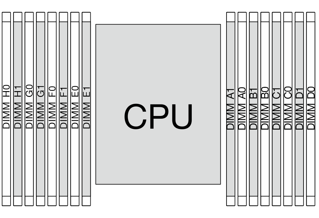
| Processor | CPU | |||||||||||||||
| Controller | iMC3 | iMC2 | iMC0 | iMC1 | ||||||||||||
| Channel | CH1 | CH0 | CH1 | CH0 | CH0 | CH1 | CH0 | CH1 | ||||||||
| Slot No. | 0 | 1 | 0 | 1 | 0 | 1 | 0 | 1 | 1 | 0 | 1 | 0 | 1 | 0 | 1 | 0 |
| DIMM No. | H0 | H1 | G0 | G1 | F0 | F1 | E0 | E1 | A1 | A0 | B1 | B0 | C1 | C0 | D1 | D0 |
Slot No.: DIMM slot number in each memory channel. Each memory channel has two DIMM slots: slot 0 (further from the processor) and slot 1 (closer to the processor).
DIMM No.: DIMM slot number helps identify the order of DIMM installation.
Memory module installation guideline
- For the installation rules and population sequence, see DDR5 DIMMs installation order.
At least one DIMM is required for the processor. Install at least eight DIMMs for good performance.
Give documentation feedback