Installing a memory module
The following notes describe the types of DIMMs that the compute node supports and other information that you must consider when you install DIMMs.
- When you install or remove DIMMs, the compute node configuration information changes. When you restart the compute node, the system displays a message that indicates that the memory configuration has changed.
- The compute node supports only industry-standard double-data-rate 3 (DDR3), 1066, 1333, 1600, or 1866 MHz, PC3-8500, PC3-10600, PC3-12800, or PC3-14900 registered or unbuffered, synchronous dynamic random-access memory (SDRAM) dual inline memory modules (DIMMs) with error correcting code (ECC). See Lenovo ServerProven compatability for a list of supported memory modules for the compute node.
- The specifications of a DDR3 DIMM are on a label on the DIMM, in the following format.
gggggeRxff PC3v-wwwwwm-aa-bb-ccd
where:- ggggg is the total capacity of the DIMM (for example, 1 GB, 2 GB, or 4 GB)
- eR is the number of ranks
- 1R = single-rank
- 2R = dual-rank
- 4R = quad-rank
- xff is the device organization (bit width)
- x4 = x4 organization (4 DQ lines per SDRAM)
- x8 = x8 organization
- x16 = x16 organization
- v is the SDRAM and support component supply voltage (VDD)
- Blank = 1.5 V specified
- L = 1.35 V specified, 1.5 V operableNoteValues for these voltages are
specified
which means the device characteristics such as timing are supported at this voltage. Values areoperable
which means that the devices can be operated safely at this voltage. However, device characteristics such as timing may not be guaranteed. All devices must betolerant
of the highest DDR3 nominal voltage of 1.5 V, meaning that they may not operate at 1.5 V but may be powered at that voltage without damage to the devices.
- wwwww is the DIMM bandwidth, in MBps
- 6400 = 6.40 GBps (DDR3-800 SDRAMs, 8-byte primary data bus)
- 8500 = 8.53 GBps (DDR3-1066 SDRAMs, 8-byte primary data bus)
- 10600 = 10.66 GBps (DDR3-1333 SDRAMs, 8-byte primary data bus)
- 12800 = 12.80 GBps (DDR3-1600 SDRAMs, 8-byte primary data bus)
- 14900 = 14.93 GBps (DDR3-1866 SDRAMs, 8-byte primary data bus)
- m is the DIMM type
- E = Unbuffered DIMM (UDIMM) with ECC (x72-bit module data bus)
- L = Load Reduction DIMM (LRDIMM)
- R = Registered DIMM (RDIMM)
- U = Unbuffered DIMM with no ECC (x64-bit primary data bus)
- aa is the CAS latency, in clocks at maximum operating frequency
- bb is the JEDEC SPD Revision Encoding and Additions level
- cc is the reference design file for the design of the DIMM
- d is the revision number of the reference design of the DIMM
NoteTo determine the type of a DIMM, see the label on the DIMM. The information on the label is in the format xxxxxnRxxx PC3v-xxxxxx-xx-xx-xxx. The numeral in the sixth numerical position indicates whether the DIMM is single-rank (n=1), dual-rank (n=2), or quad-rank (n=4). - The specifications of a DDR3 DIMM are on a label on the DIMM, in the following format.
- The following rules apply to DDR3 RDIMM speed as it relates to the number of RDIMMs in a channel:
- When you install 1 RDIMM per channel, the memory runs at 1866 MHz
- When you install 2 RDIMMs per channel, the memory runs at 1600 MHz
- When you install 3 RDIMMs per channel, the memory runs at 1066 MHz
- All channels in a compute node run at the fastest common frequency
- Do not install registered, unbuffered, and load reduction DIMMs in the same compute node
- The maximum memory speed is determined by the combination of the microprocessor, DIMM speed, DIMM type, Operating Modes in UEFI settings, and the number of DIMMs installed in each channel.
- In two-DIMM-per-channel configuration, the compute node automatically operates with a maximum memory speed of up to 1600 MHz when the following condition is met:
- Two 1.35 V single-rank, dual-ranl, or quad-rank UDIMMs, RDIMMs or LRDIMMs are installed in the same channel. In the Setup utility, Memory speed is set to Max performance and LV-DIMM power is set to Enhance performance mode. The 1.35 V UDIMMs, RDIMMs or LRDIMMs will function at 1.5 V.
- The compute node supports a maximum of 8 dual-rank UDIMMs. The compute node supports up to one UDIMMs per channel.
- The compute node supports a maximum of 8 dual-rank RDIMMs. The compute node supports up to one RDIMMs per channel.
- The following table shows an example of the maximum amount of memory that you can install using ranked DIMMs:
Table 1. Maximum memory installation using ranked DIMMs. Four column table documenting the total memory with different configurations.
Number of DIMMs DIMM type DIMM size Total memory 8 Dual-rank UDIMM 4 GB 32 GB 8 Single-rank RDIMM 4 GB 32 GB 8 Dual-rank RDIMM 4 GB 32 GB 8 Single-rank RDIMM 8 GB 64 GB 8 Dual-rank RDIMM 8 GB 64 GB 8 Dual-rank RDIMM 16 GB 128 GB - The UDIMM option that is available for the compute node is 4 GB. The compute node supports a minimum of 4 GB and a maximum of 32 GB of system memory using UDIMMs.
- The RDIMM options that are available for the compute node are 4 GB, 8 GB, and 16 GB. The compute node supports a minimum of 4 GB and a maximum of 128 GB of system memory using RDIMMs.
- A minimum of one DIMM must be installed for each microprocessor. For example, you must install a minimum of two DIMMs if the compute node has two microprocessors installed. However, to improve system performance, install a minimum of four DIMMs for each microprocessor.
- DIMMs in the compute node must be the same type (RDIMM or UDIMM) to ensure that the compute node will operate correctly.
- When you install one quad-rank DIMM in a channel, install it in the DIMM connector furthest away from the microprocessor.
Note
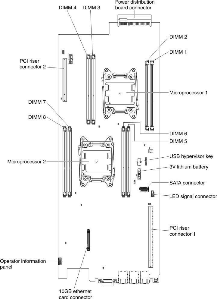
- You can install DIMMs for microprocessor 2 as soon as you install microprocessor 2; you do not have to wait until all of the DIMM slots for microprocessor 1 are filled.
- DIMM slots 5-8 are reserved for microprocessor 2; thus, DIMM slots 5-8 are enabled when microprocessor 2 is installed.
The following illustration shows the location of the DIMM connectors on the system board.
Figure 1. DIMM connectors location
Give documentation feedback