Install the bus bar connector module
Use this information to install the bus bar connector module.
About this task
Screwdriver for PH1 and PH 2 screws
Read Installation Guidelines and Safety inspection checklist to ensure that you work safely.
The following illustration might differ slightly from your hardware, but the installation method is the same.
Go to Drivers and Software download website for ThinkSystem SC750 V4 to see the latest firmware and driver updates for your server.
Go to Update the firmware for more information on firmware updating tools.
- A video of this procedure is available at YouTube.
Procedure
- Install the bus bar connector module.
 Install the bus bar connector module to the tray rear bezel.
 Install three PH1 screws on the rear tray bezel.Figure 1. Installing the bus bar connector module
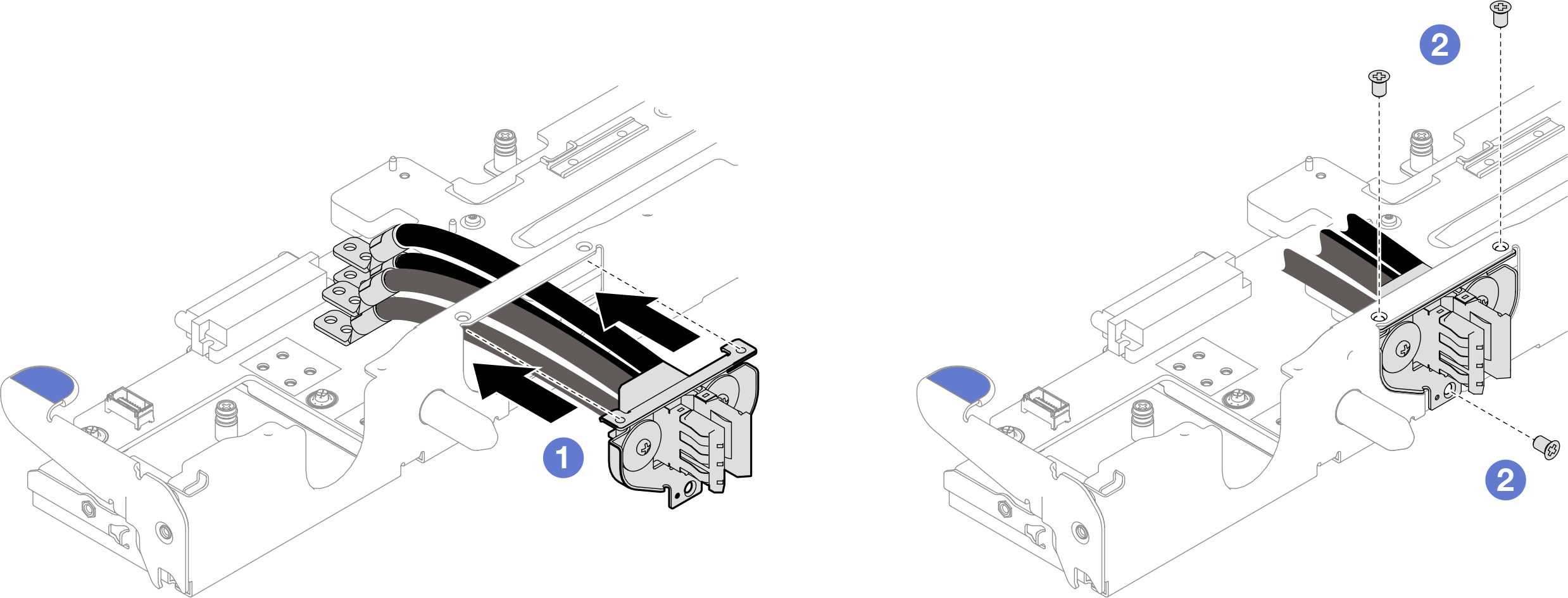
 Take the cables labeled as PWR and connect them to the power pad marked as PWR. Install four PH2 screws to secure the cables to the PIB, with a torque screwdriver set to the proper torque.
 Take the cables labeled as GND and connect them to the ground pad marked as GND. Install four PH2 screws to secure the cables to the PIB, with a torque screwdriver set to the proper torque.
NoteFor reference, the torque required for the screws to be fully tightened/removed is 7+/- 1.0 lbf-in.
Figure 2. Connecting the bus bar connector module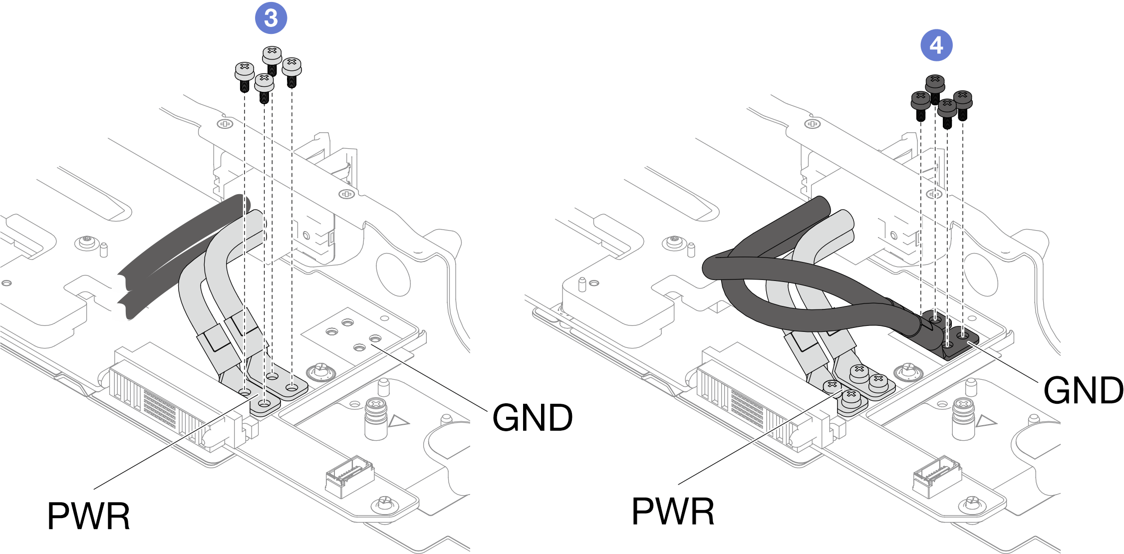
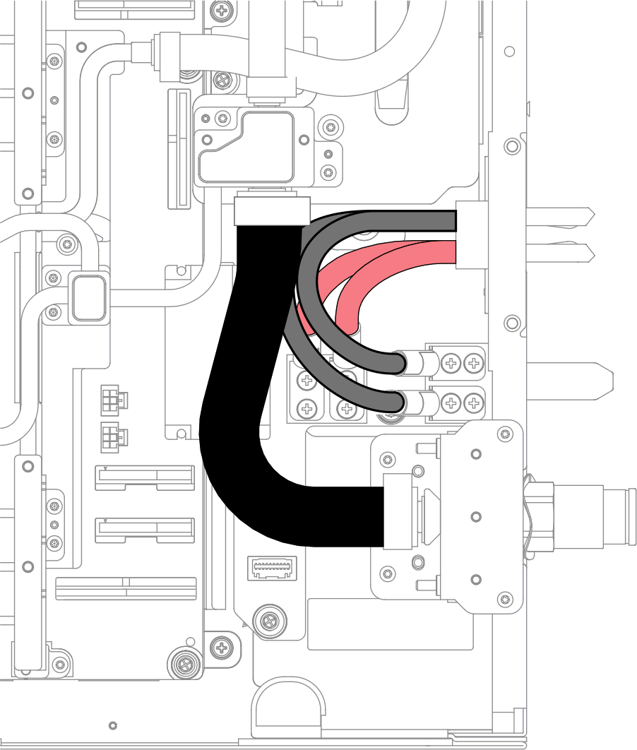
- Place one GND cable under the water loop tube, the other GND cable between the tube and the PWR cables, as the illustration below.Figure 3. GND cable arrangement
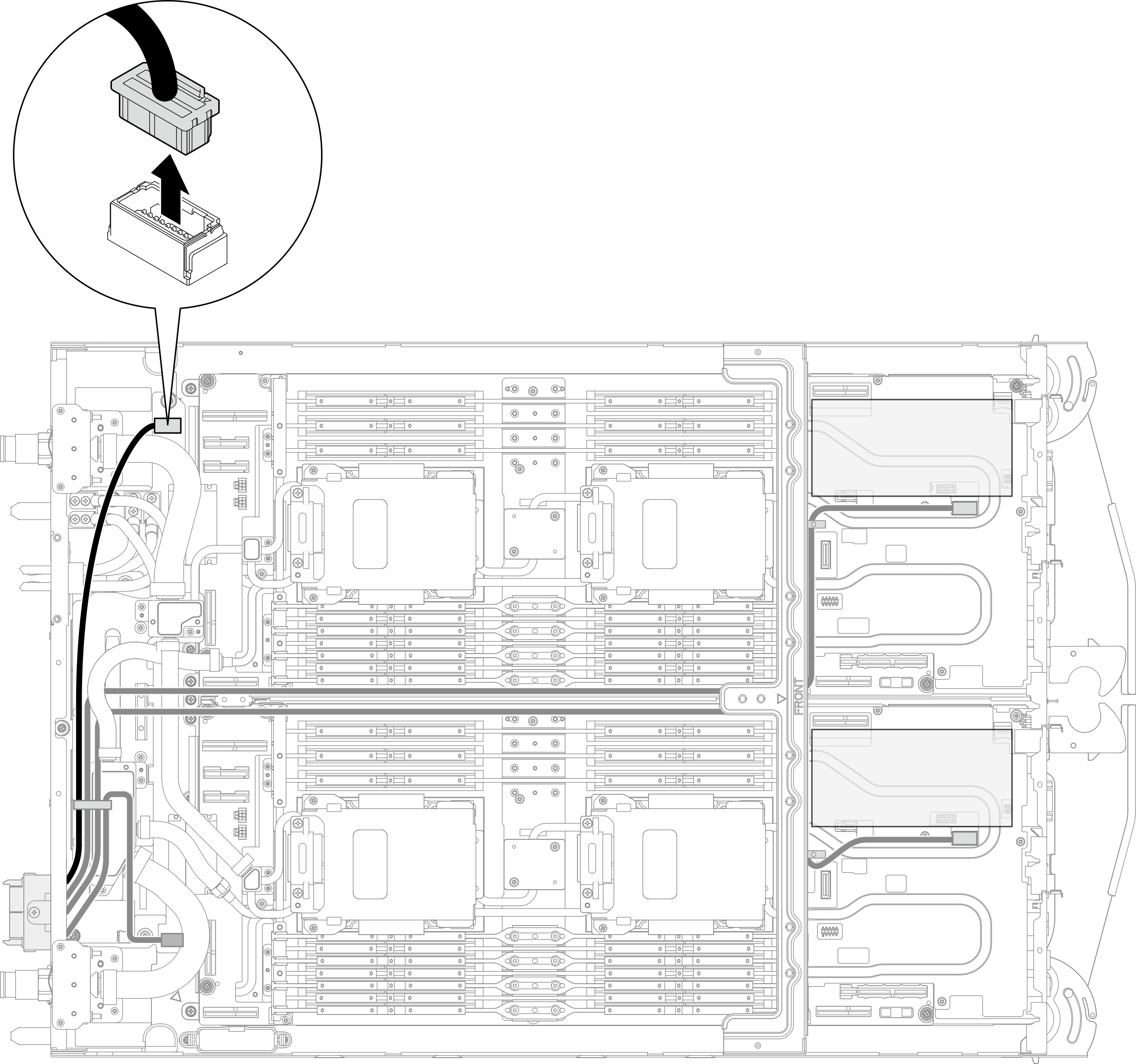
- Connect the sideband cable that has P3 marked on its plugger to the PDB.Figure 4. Connecting the P3 sideband cable
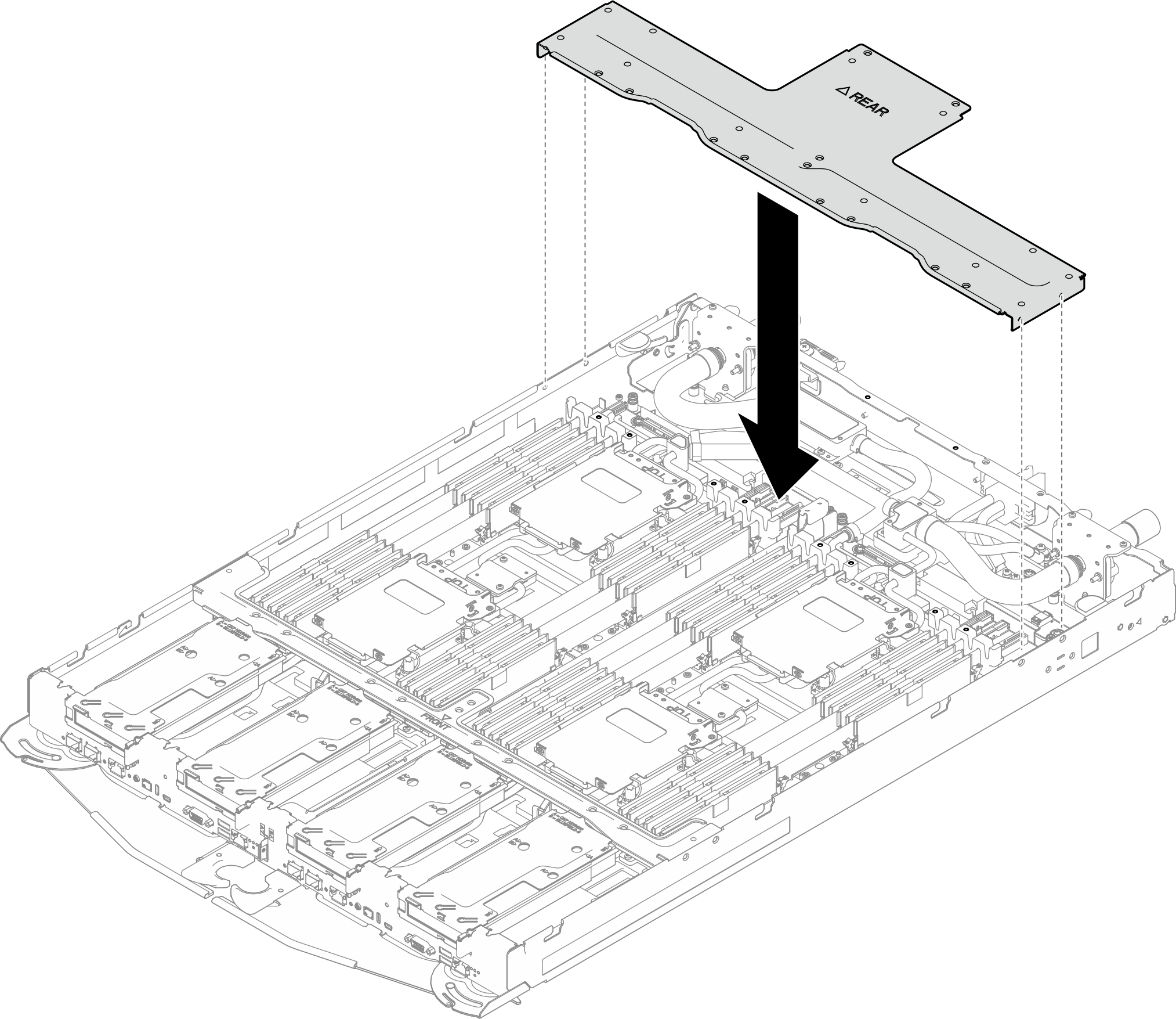
- Place the rear cross brace on the tray.Figure 5. Placing rear cross brace on the tray
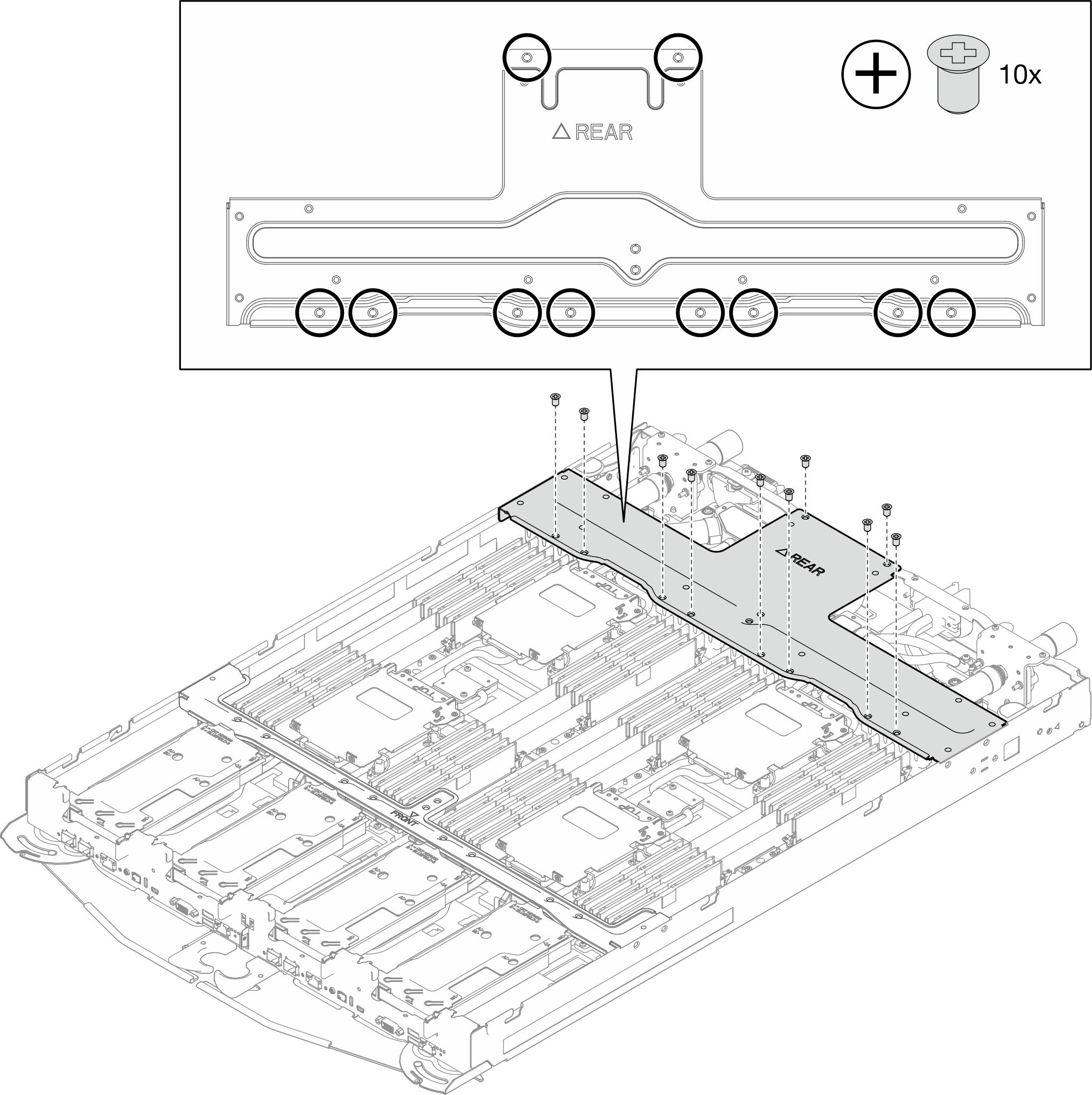
- Install the rear cross braces to the tray.
- Install ten (10x) PH1 screws to secure the rear cross brace.Figure 6. Installing screws to the rear cross brace (10x)
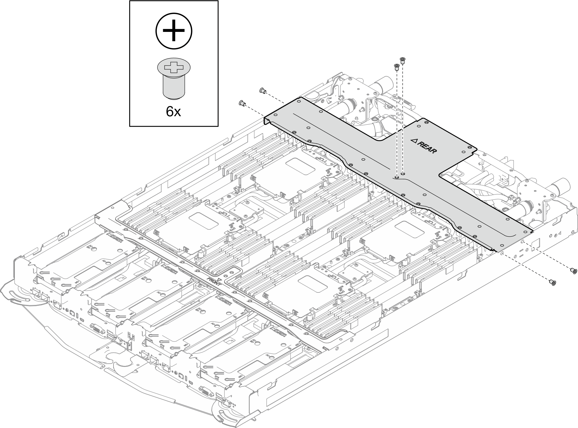
- Fasten six (6x) PH1 screws to install the cross braces.Figure 7. Installing screws to the rear cross brace (6x)
- Install ten (10x) PH1 screws to secure the rear cross brace.
Install the tray cover. See Install the tray cover.
Install the tray into the enclosure. See Install a tray in the enclosure.
- Connect all required external cables to the solution.NoteUse extra force to connect QSFP cables to the solution.
- Check the power LED on each node to make sure it changes from fast blink to slow blink to indicate all nodes are ready to be powered on.Note
Shared I/O configuration requires specific nodes power-on sequence. When powering on the system, power on Node B first; then, power on Node A. For more information, see PCIe adapter cable routing.