KVM breakout module
Use this section to understand how to route cables for your KVM breakout module.
Note
If you are installing NVMe drives and KVM breakout module in the same compute node, make sure to route the KVM breakout module cable on top of the PCIe signal cable.
Figure 1. NVMe and KVM breakout module cable routing
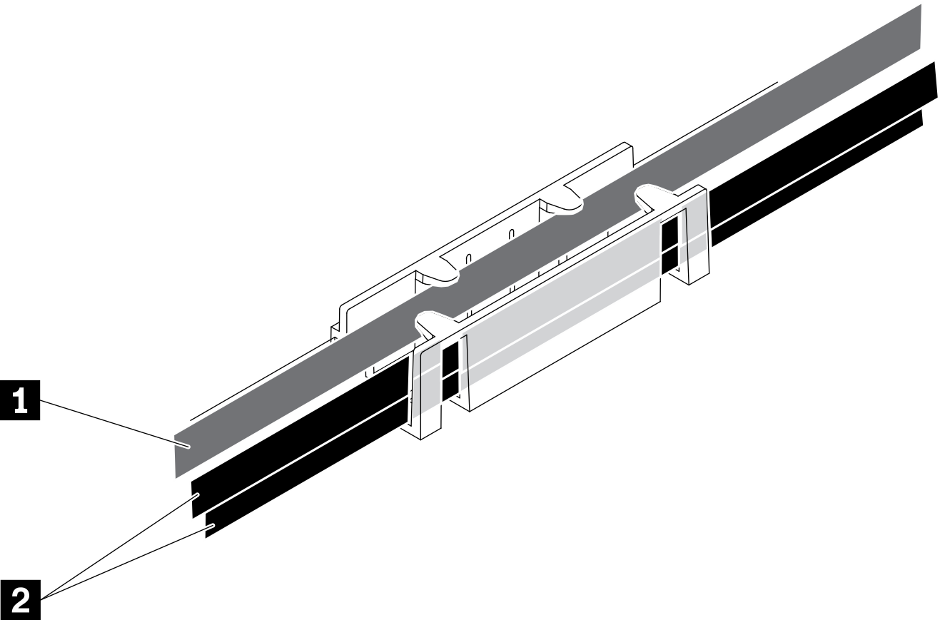
| 1 KVM breakout module cable (routed to left side) | 2 NVMe signal cables |
The right KVM breakout module (for four 2.5-inch-drive model)
Figure 2. KVM breakout module installed in drive bay 4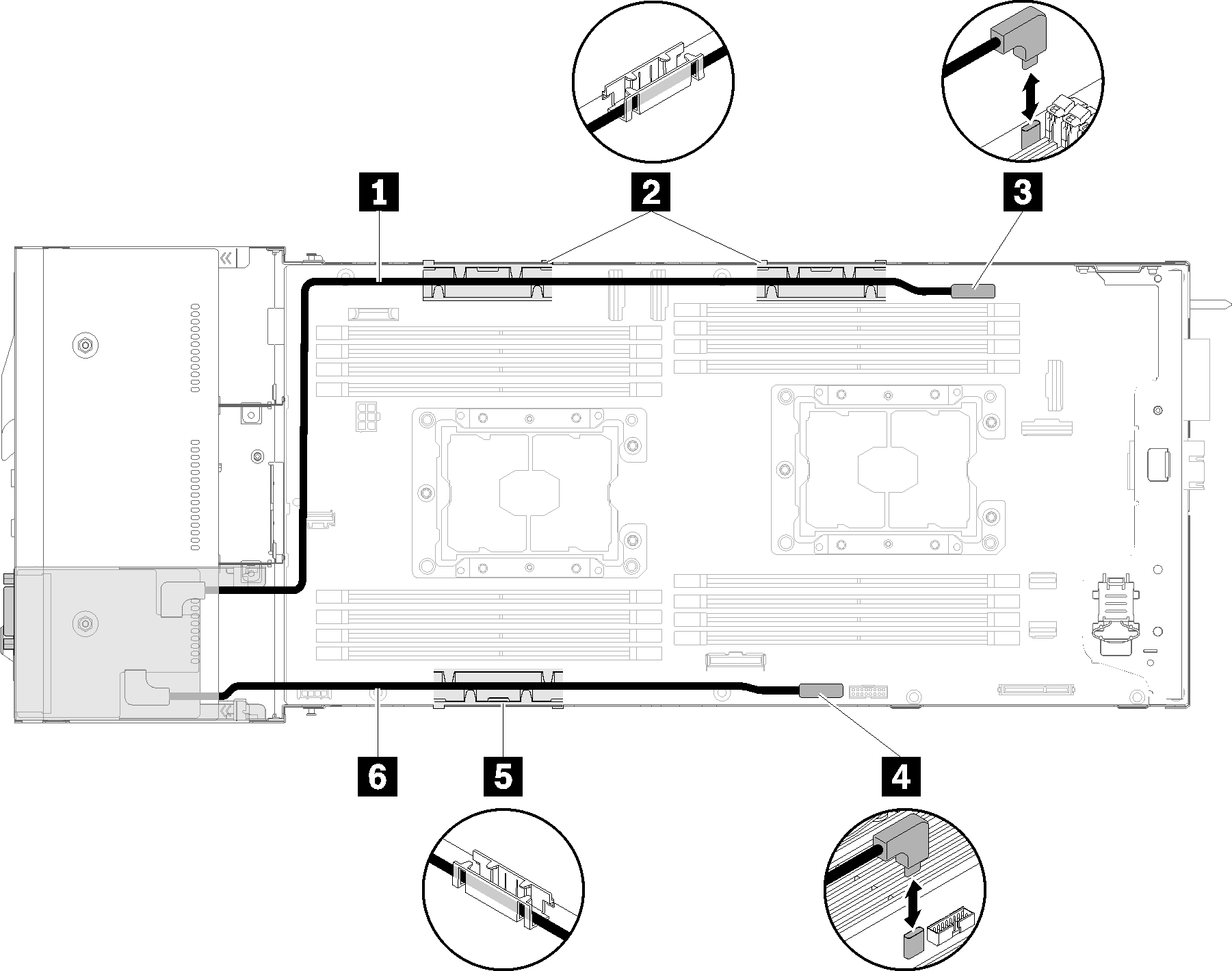
Table 2. Components on the KVM breakout module installed in drive bay 4 1 Long signal cable 3 KVM breakout cable connector 2 5 Internal cable management basket 4 USB connector 6 Short signal cable The left KVM breakout module (for six 2.5-inch-drive model)
Figure 3. KVM breakout module installed in drive bay 0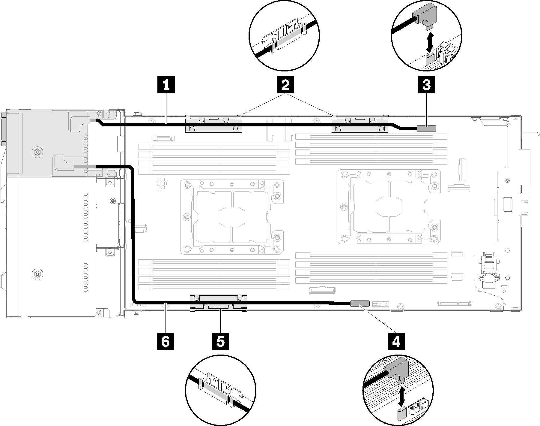
Table 3. Components on the KVM breakout module installed in drive bay 0 1 Short signal cable 3 KVM breakout cable connector 2 5 Internal cable management basket 4 USB connector 6 Long signal cable
Give documentation feedback