Install the PCIe expansion node to a compute node
Use this information to install the PCIe expansion node to a compute node.
- Read the following section(s) to ensure that you work safely.
Make sure the compute node configuration meets the following requirements.
No RAID adapter should be installed in the compute node.
Only four-drive backplanes are supported.
No more than 12 DIMMs should be installed in the compute node.
When two GPU adapters are installed:
Two processors are required in the compute node.
Four-drive NVMe backplane is not supported.
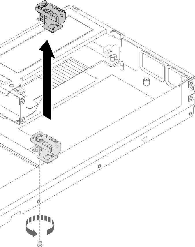
- Remove the screw that secures the cable bracket to the expansion node, and remove the cable bracket.Figure 1. Cable bracket removal from the expansion node
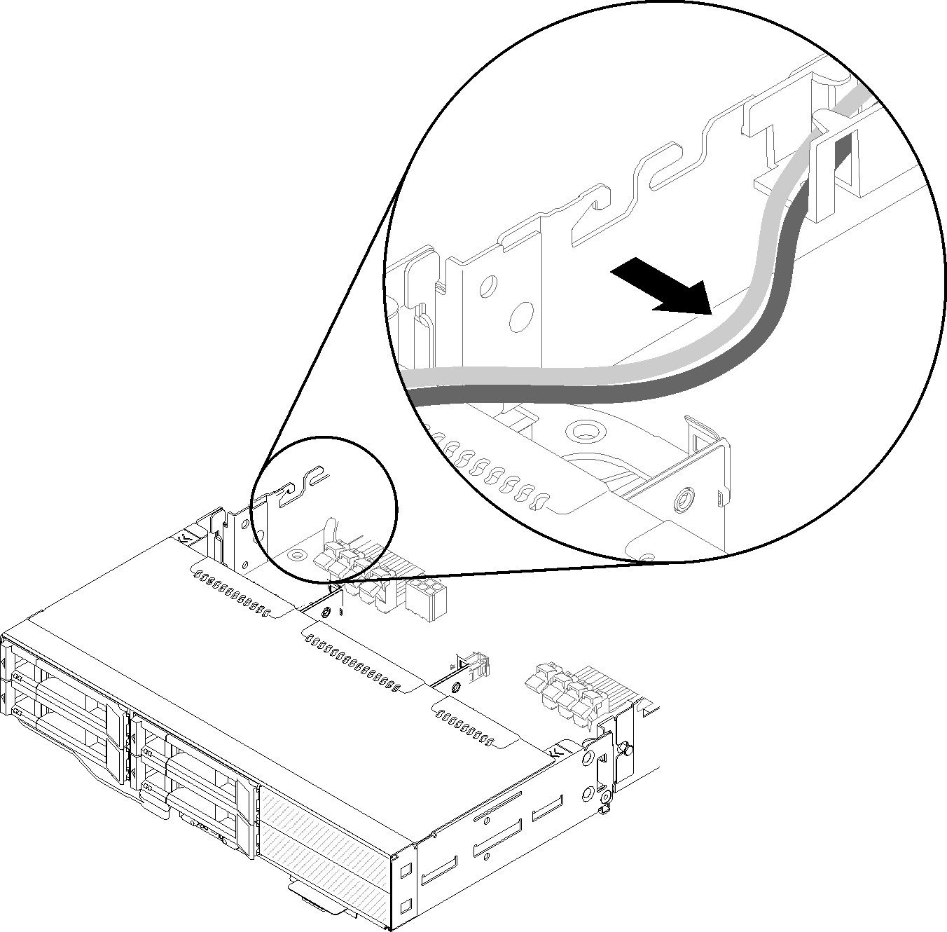
- Pull the cables on the side of the compute node slightly to make space for the cable bracket.Figure 2. Pulling the cables to make space for the cable bracket
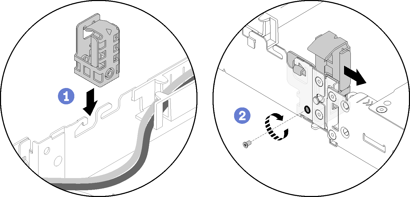
- Align the hook on the cable bracket to the slot on the side of the compute node as illustrated, and lower it until it stops.Figure 3. Cable bracket installation to the compute node
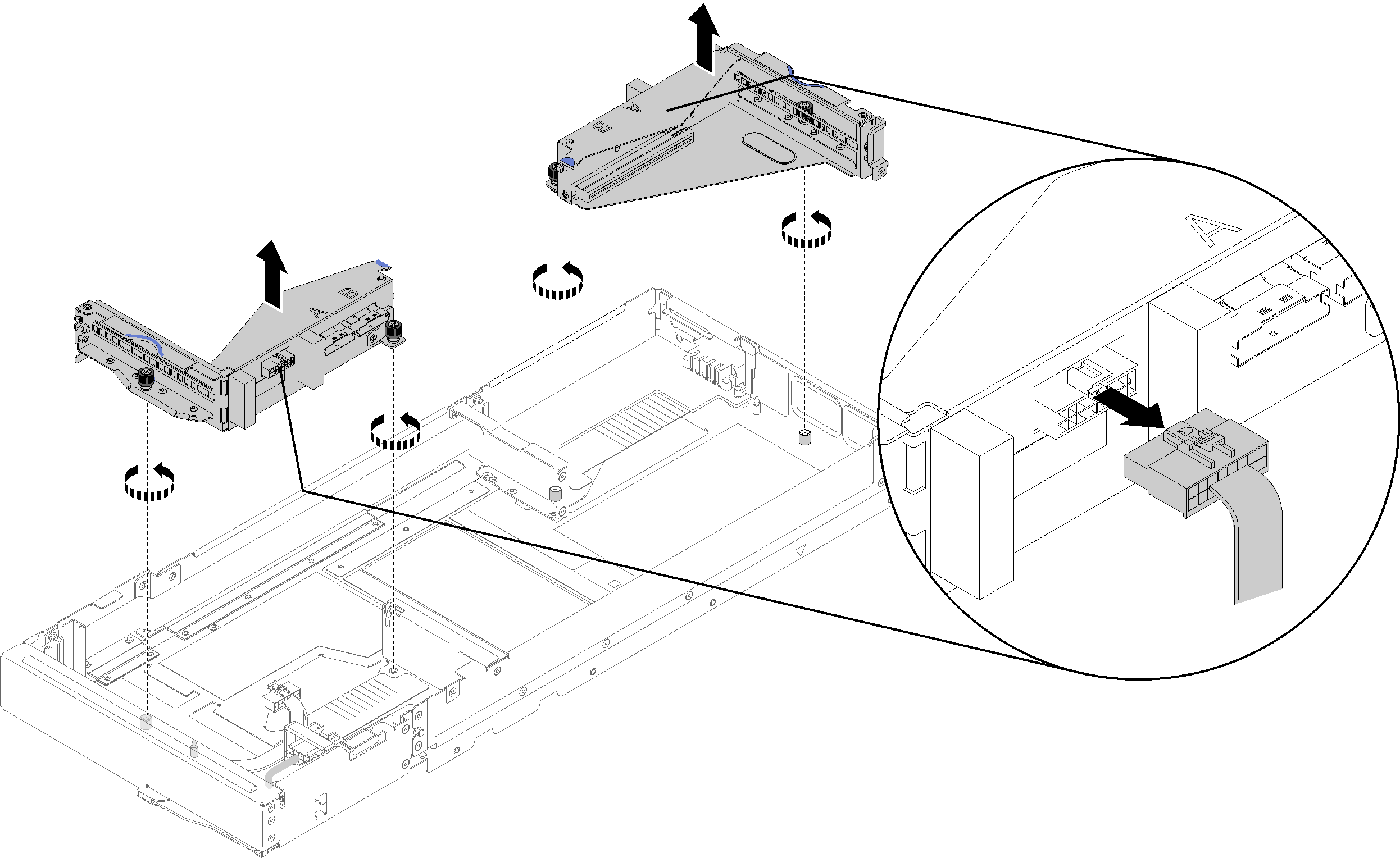
- Disconnect the front riser miscellaneous cable from the front riser cage; then, loosen the two captive screws from each riser cage, and remove the riser cages from the expansion node.NoteIf you only plan to install one adapter, remove the rear riser cage only.Figure 4. Disconnecting the front riser miscellaneous cable and removing riser cages from the expansion node
- Connect PCIe#3-A and PCIe#4-B cable to the compute node as illustrated.Figure 5. Connecting PCIe#3-A and PCIe#4-B cable to the compute node
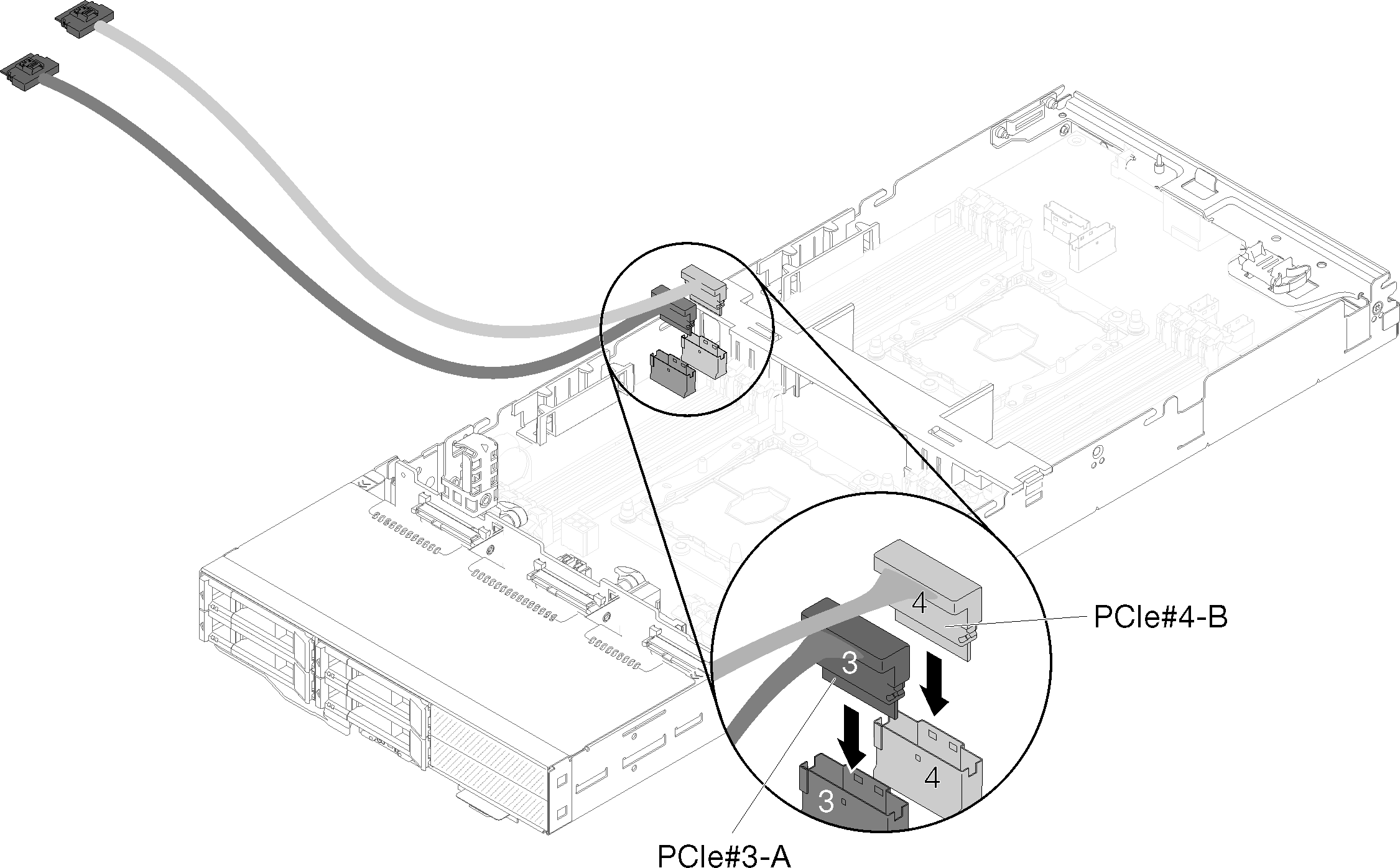 NoteKeep the caps on PCIe cable connectors until connecting the cables to the compute node or to the riser assemblies.
 - Pass the cables through the cable guide based on the following compute node configurations.
When the compute node comes with the right KVM breakout module, pass the cables in the following order, one at a time:
- PCIe#3-A cable
- PCIe#4-B cable
- Long KVM signal cable
- SAS/SATA cable
When the compute node comes without the right KVM breakout module, pass the cables in the following order, one at a time:- SAS/SATA cableNoteWhen you install a KVM breakout module, make sure the other signal cable passes through the cable guide on the other side of the compute node (see
KVM breakout module). Figure 6. Passing cables through the cable guide and the cable bracket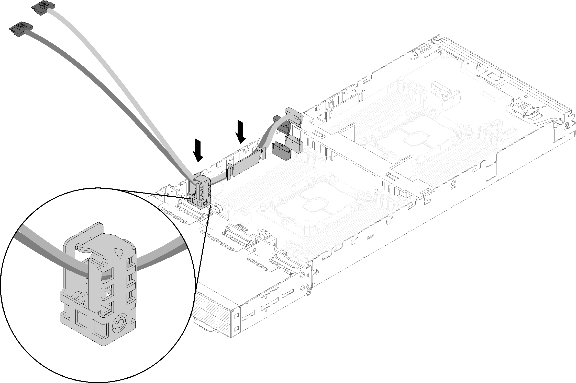
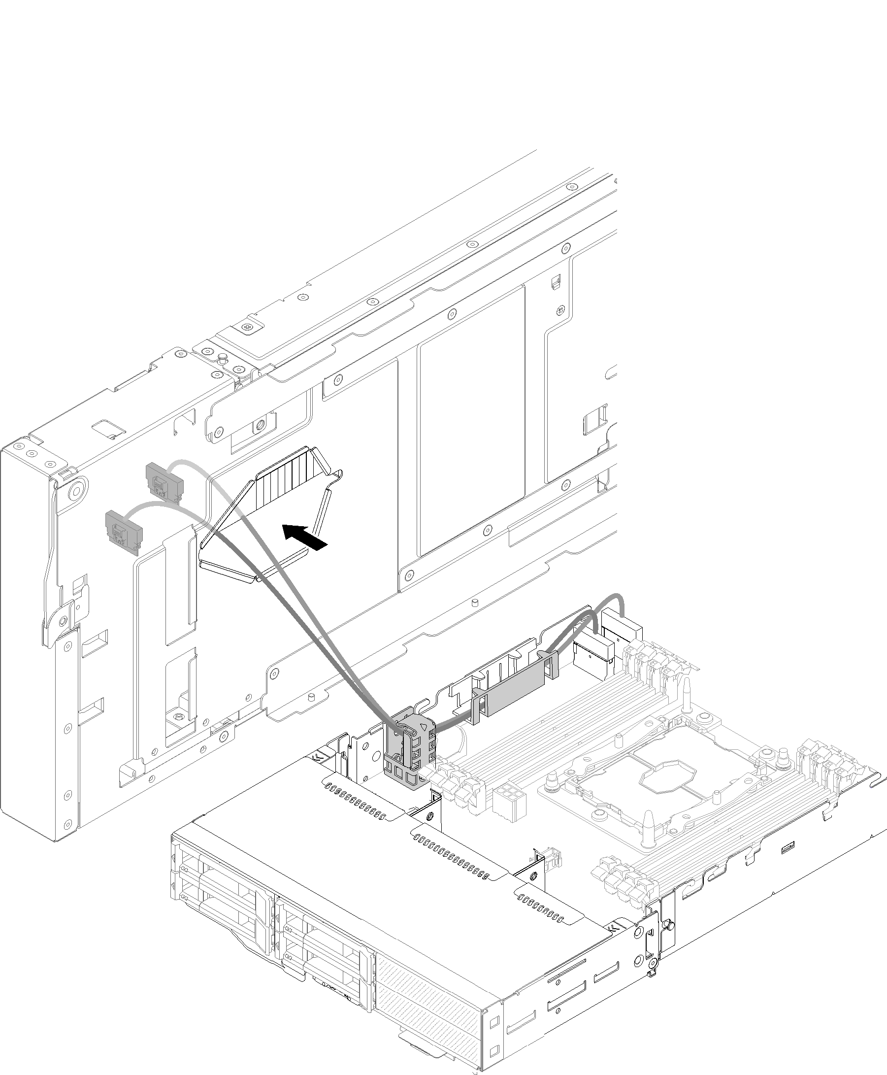
- Face the bottom of the expansion node next to the cable bracket; then, pass PCIe#3-A and PCIe#4-B cable through the underside of the expansion node as illustrated.Figure 7. Passing PCIe#3-A and PCIe#4-B cable through the expansion node
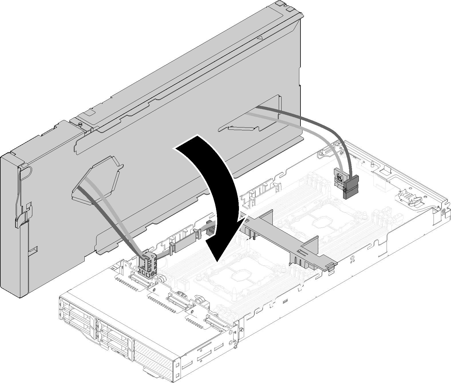
- Pivot the expansion node over the top of the compute node.Figure 8. Pivoting the expansion node over the top of the compute node
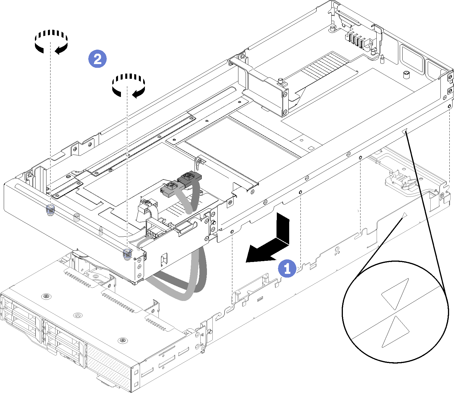
- Align the triangles located on the sides of both the expansion node and the compute node; then, slide the expansion node slightly forward, and secure it by tightening the two captive screws near the front of the expansion node.Figure 9. Engaging the expansion node to the compute node
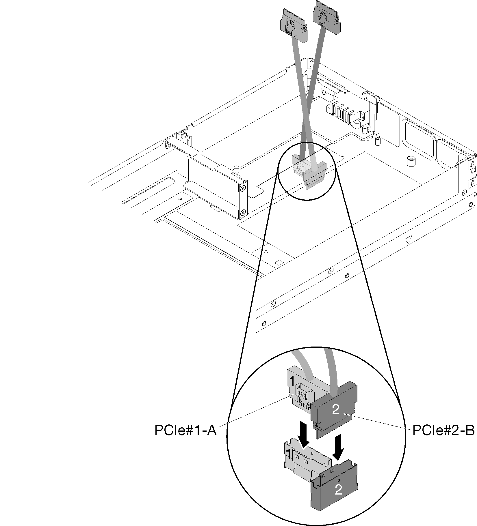
- Route PCIe#1-A and PCIe#2-B cable down through the expansion node from top side, and connect them to the compute node connectors as illustrated. Figure 10. Connecting PCIe#1-A and PCIe#2-B cable to the compute node
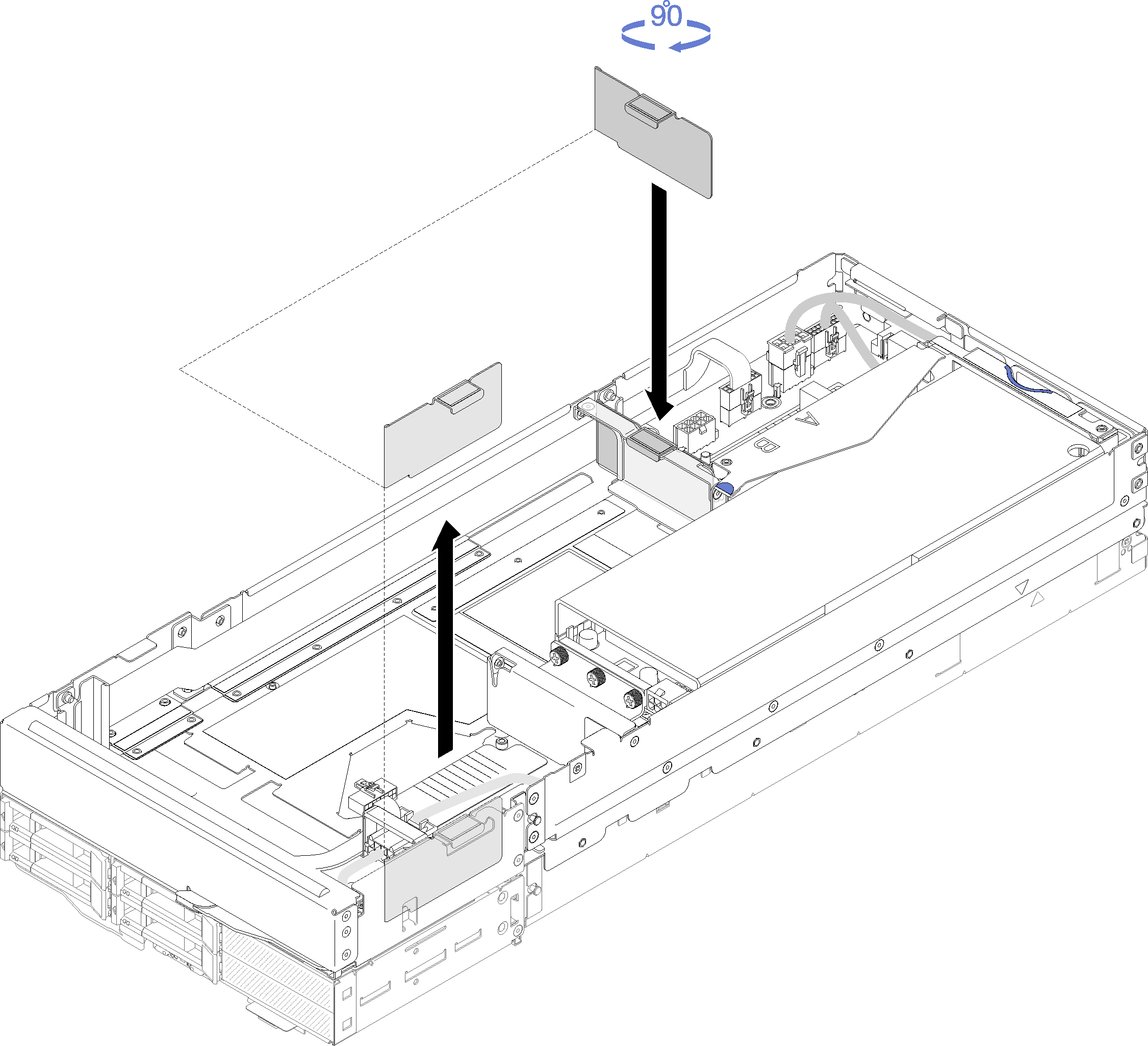
- If only one adapter is installed in the expansion node (in the rear riser slot), make sure to remove the airflow filler from the side of the expansion node, and place it in the slot by the front riser slot.Figure 11. Airflow filler installation
After you install the PCIe expansion node to the compute node, complete the following steps:
Install the PCIe expansion node assembly into the enclosure (see Install the compute-expansion node assembly into the enclosure).
Power on the compute node.