Re-engage the PCIe expansion node to a compute node
Use this information to re-engage the PCIe expansion node to the compute node after finishing replacing components in the compute node.
Before you re-engage the PCIe expansion node to a compute node:
- Read the following section(s) to ensure that you work safely.
Make sure all disconnected cables in the compute node are re-connected.
Make sure all components removed from the compute node are reinstalled, particularly the air baffle.
Complete the following steps to re-engage the PCIe expansion node to a compute node.
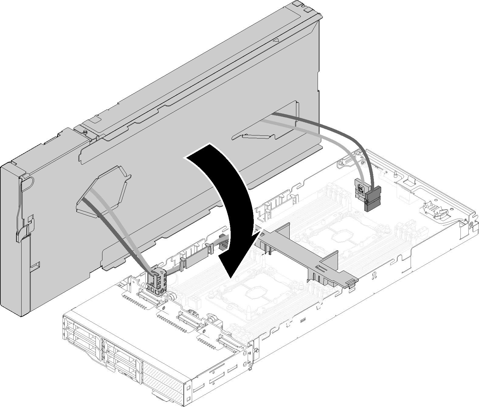
- Pivot the expansion node over the top of the compute node.Figure 1. Pivoting the expansion node over the top of the compute node
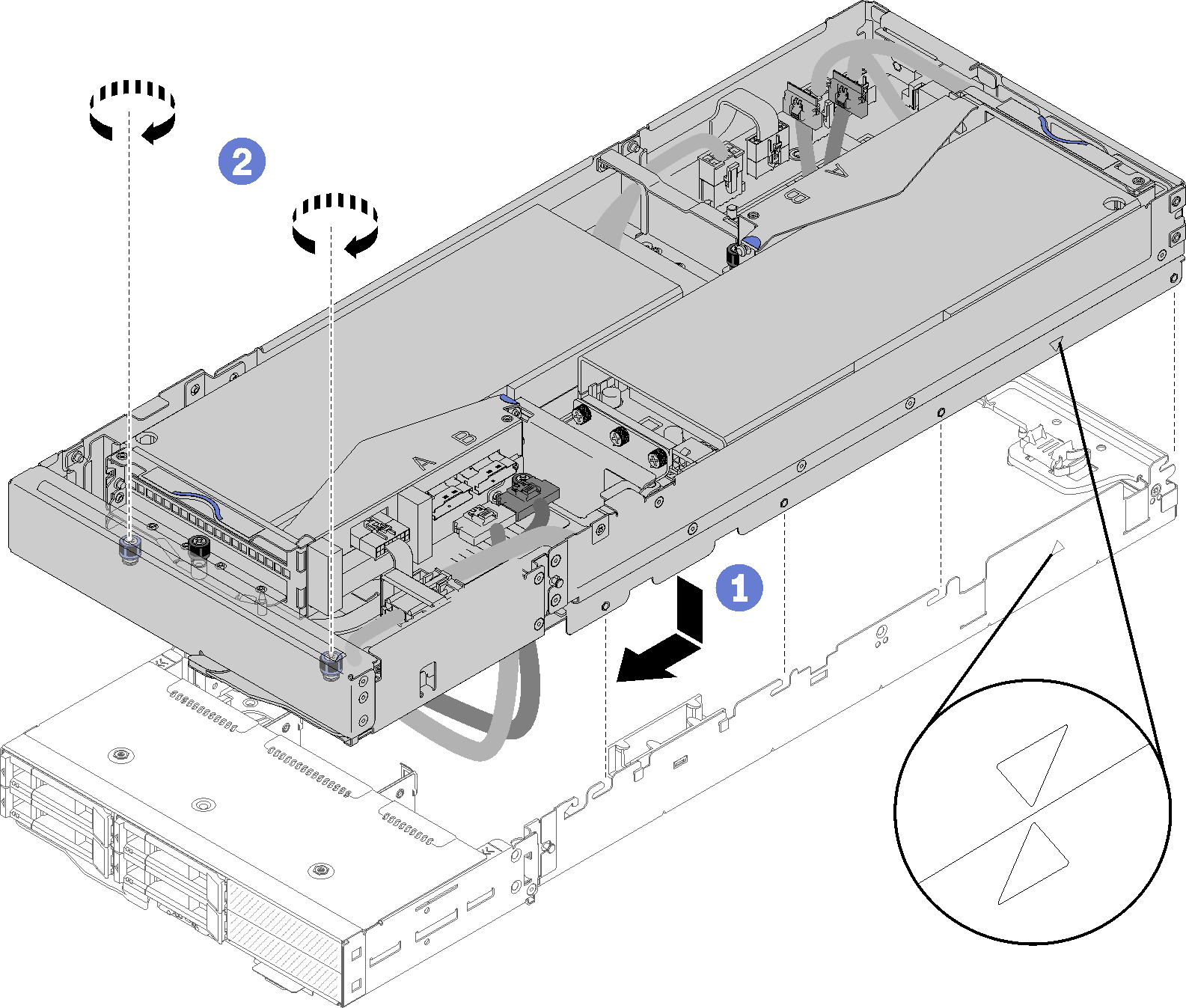
- Align the triangles located on the sides of both the expansion node and the compute node; then, slide the expansion node slightly forward, and secure it by tightening the two captive screws near the front of the expansion node.Figure 2. Re-engaging the expansion node to the compute node
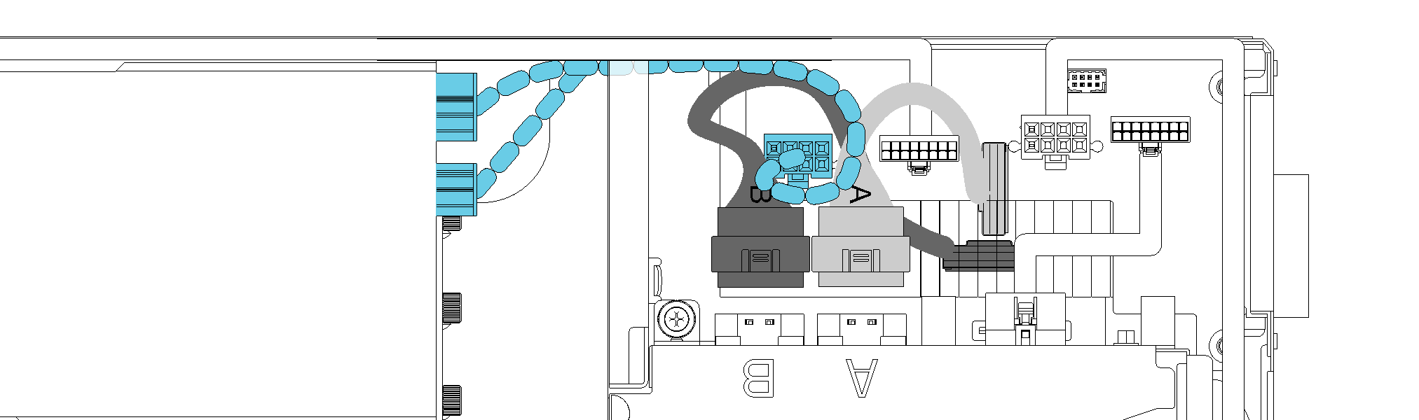
- Route PCIe#2-B cable between the two front riser power connectors, below the front riser auxiliary power cable, and connect it to the riser connector labeled “B.” Figure 3. Routing PCIe#1-A and PCIe#2-B cable
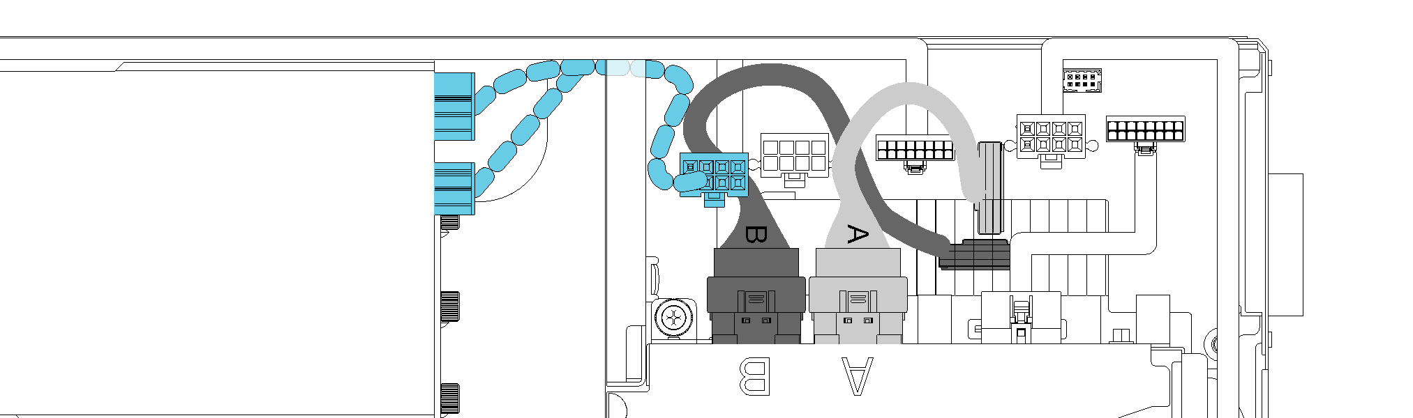
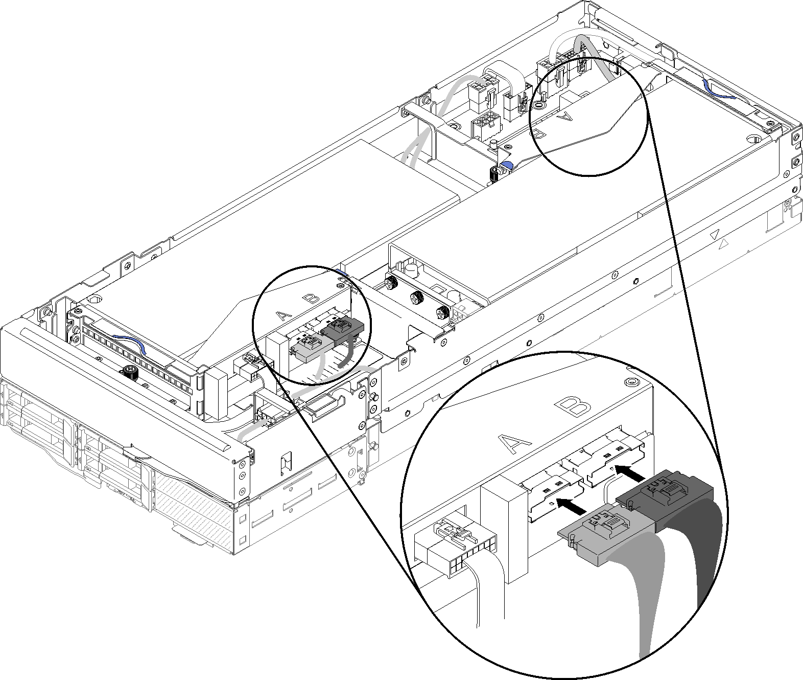
- Connect PCIe#3-A cable to the riser connector labeled “A.”Figure 4. Connecting the four PCIe cables
After you re-engage the PCIe expansion node to a compute node, complete the following steps:
- If the front riser auxiliary power cable has been disconnected, reconnect it to the expansion node.Figure 5. Reconnecting the auxiliary cable of the front riser assembly to the expansion node
Install the rear cable cover (see Install the rear cable cover).
Install the PCIe expansion node assembly into the enclosure (see Install the compute-expansion node assembly into the enclosure).
Power on the compute node.
Demo video
Give documentation feedback