Lenovo Processor Neptune® Core Module 제거
이 섹션의 지침에 따라 Processor Neptune® Core Module을(를) 제거하십시오. 이 절차는 숙련된 기술자가 수행해야 합니다.
이 작업 정보
누수 센서 모듈 케이블에 대한 안전 정보
S011

경고
날카로운 테두리, 모서리 또는 이음새 부근입니다.
주의
해당 나사를 올바르게 설치 및 제거할 수 있도록 다음 드라이버를 준비하십시오.
| 토크 드라이버 유형 목록 | 나사 유형 |
|---|---|
| Torx T20 드라이버 | Torx T20 나사 |
절차
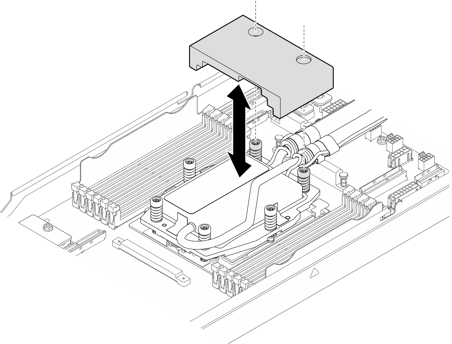
- 방열판에서 고무 공기 조절 장치를 제거합니다.그림 1. 고무 공기 조절 장치 제거
- 누수 센서 모듈을 분리하십시오.
- 홀더 래치를 양쪽으로 밀어 모듈을 잠금 해제합니다.
- 홀더에서 누수 센서 모듈을 분리합니다.
그림 2. 누수 센서 모듈 분리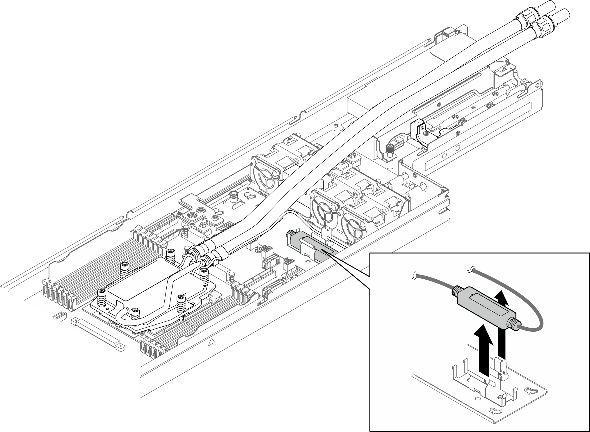
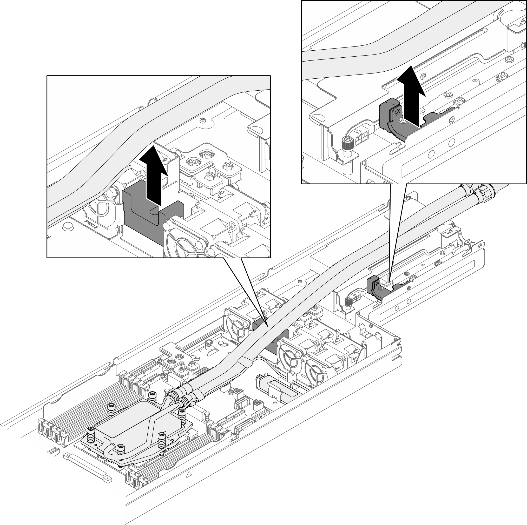
- 첫 번째 호스 덮개를 제거하십시오.
 호스 덮개를 섀시에 고정하는 나사 2개를 푸십시오.
 섀시에서 호스 덮개를 잡고 제거하십시오.
그림 3. 호스 덮개 제거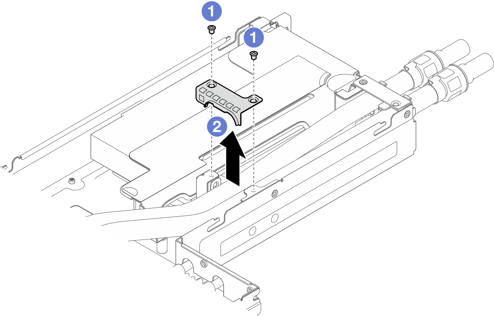
- 두 번째 호스 덮개를 제거하십시오.
- 호스 덮개를 섀시에 고정하는 나사 2개를 푸십시오.
- 섀시에서 호스 덮개를 잡고 제거하십시오.
그림 4. 호스 덮개 제거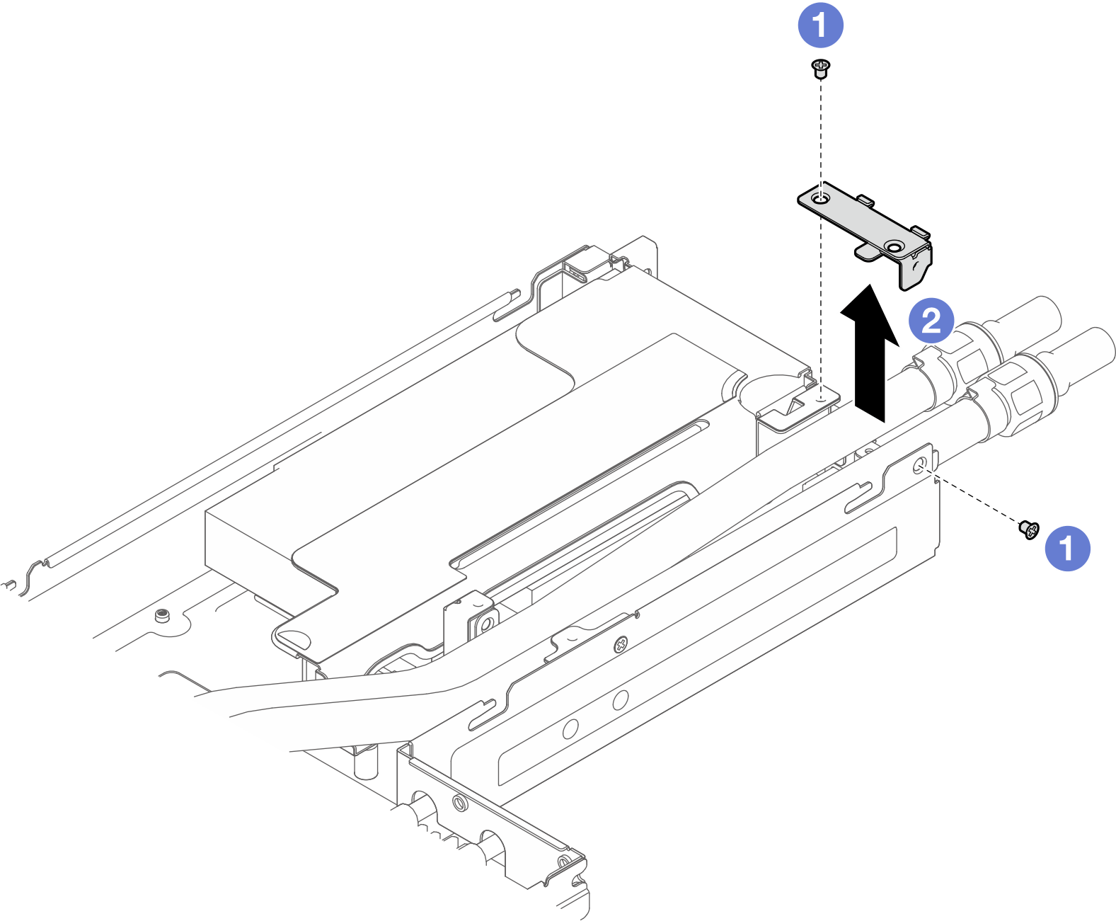
- 레이블에 표시된 제거 순서대로 냉각판의 모든 나사를 완전히 풀어 줍니다.주
프로세서 하단의 접촉부를 만지지 마십시오.
프로세서 소켓이 손상되지 않도록 모든 물체로부터 깨끗하게 유지하십시오.
필요한 경우 일자 드라이버를 사용하여 냉각판 모서리에서 냉각판과 CPU를 조심스럽게 분리합니다. CPU 또는 냉각판이 손상되지 않도록 하십시오.
그림 5. 냉각판 제거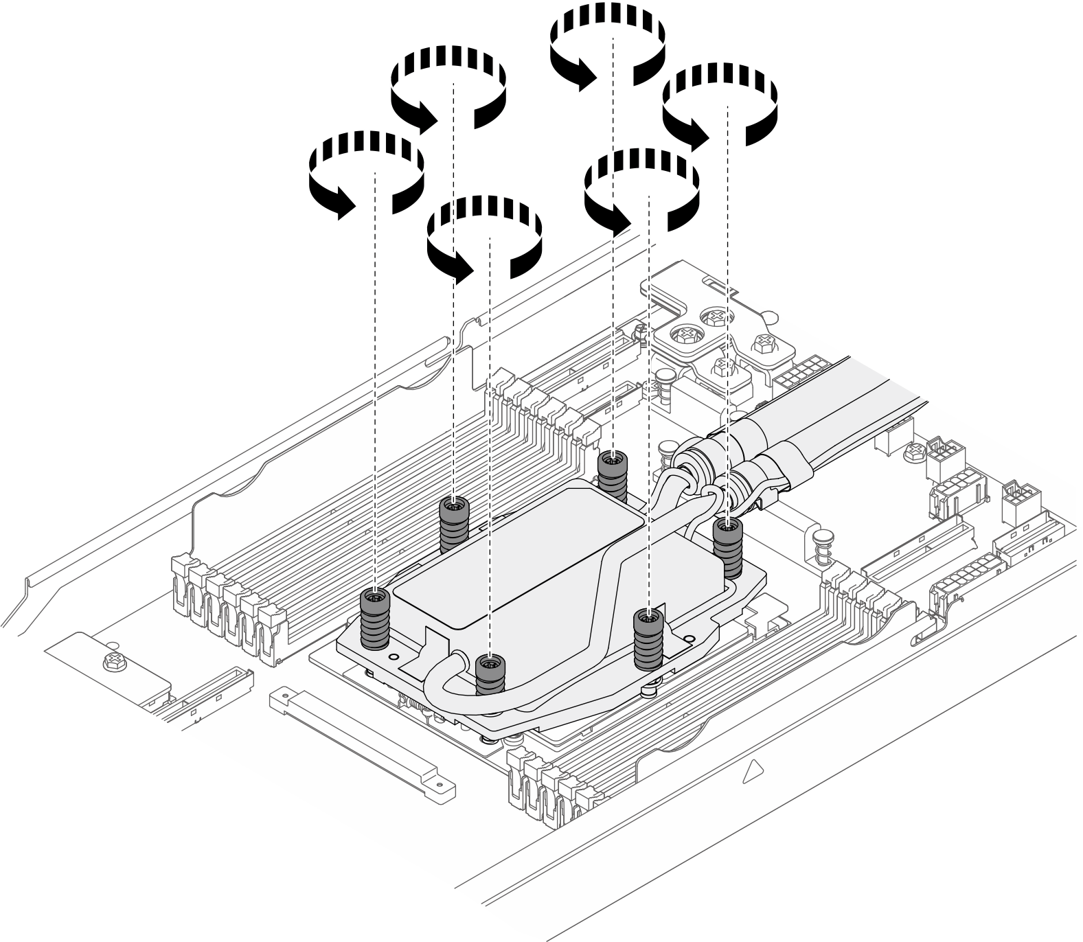
- 섀시에서 Processor Neptune® Core Module을(를) 제거하십시오.
- 호스 홀더에서 호스를 분리합니다.그림 6. 호스 분리
- 섀시에서 Processor Neptune® Core Module을(를) 제거하십시오.그림 7. 모듈 제거
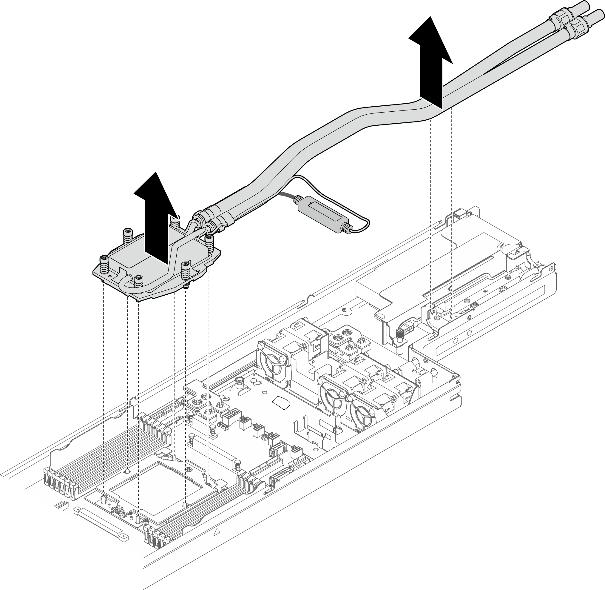
- 호스 홀더에서 호스를 분리합니다.
- 프로세서를 제거하십시오.
- Torx T20 드라이버를 사용하여 나사를 푸십시오.
- 표시된 방향으로 고정 프레임을 살짝 들어 올리십시오.
 표시된 방향으로 레일 프레임을 살짝 들어 올리십시오. 레일 프레임의 프로세서에 스프링이 장착됩니다.
 프로세서 캐리어의 파란색 탭을 잡고 프로세서 캐리어를 레일 프레임에서 빼내십시오.
그림 8. 프로세서 제거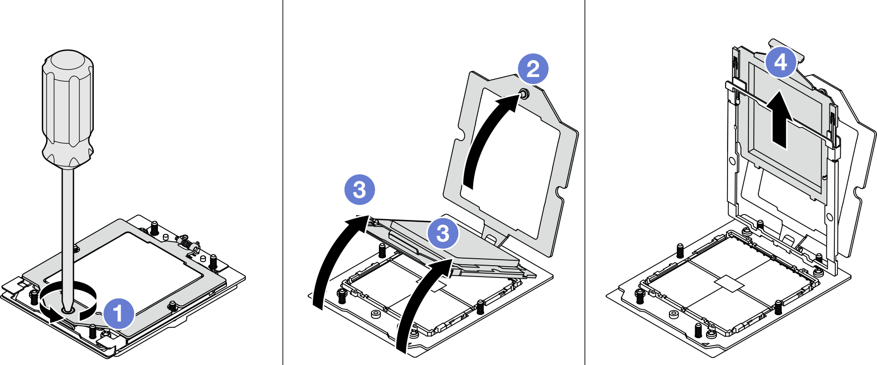
완료한 후
- 각 프로세서 소켓에는 항상 덮개 또는 프로세서와 냉각판 어셈블리가 있어야 합니다. 덮개를 사용하여 비어 있는 프로세서 소켓을 보호하거나 새 프로세서 및 냉각판 어셈블리를 설치하십시오.
- 교체 장치를 설치하십시오(Lenovo Processor Neptune® Core Module 설치 참조).
- 구성 요소 또는 옵션 장치를 반환하도록 지시받은 경우 모든 포장 지시사항을 따르고 제공되는 운송용 포장재를 사용하십시오.
데모 비디오
피드백 보내기