Remove a side bracket
Follow instructions in this section to remove a side bracket from the node.
About this task
To avoid potential danger, make sure to read and follow the safety information.
Attention
Read Installation Guidelines and Safety inspection checklist to make sure that you work safely.
Procedure
- Make preparations for this task.
- Power off the node (see Power off the node); then, disconnect all external cables from the node.NoteIf necessary, press the release clip with a flat-head screwdriver to remove an external network cable from the rear of a 2U node.

- Power off the node (see Power off the node); then, disconnect all external cables from the node.
- Remove the left side bracket from the node.
 Remove all the screws that secure the side bracket to the node.
 Hold the upper part of the side bracket and slide the side bracket toward the rear of the node to disengage it.
 Take the side bracket away from the node.ImportantStore the screws safely for future use.Figure 1. Removal of the side bracket
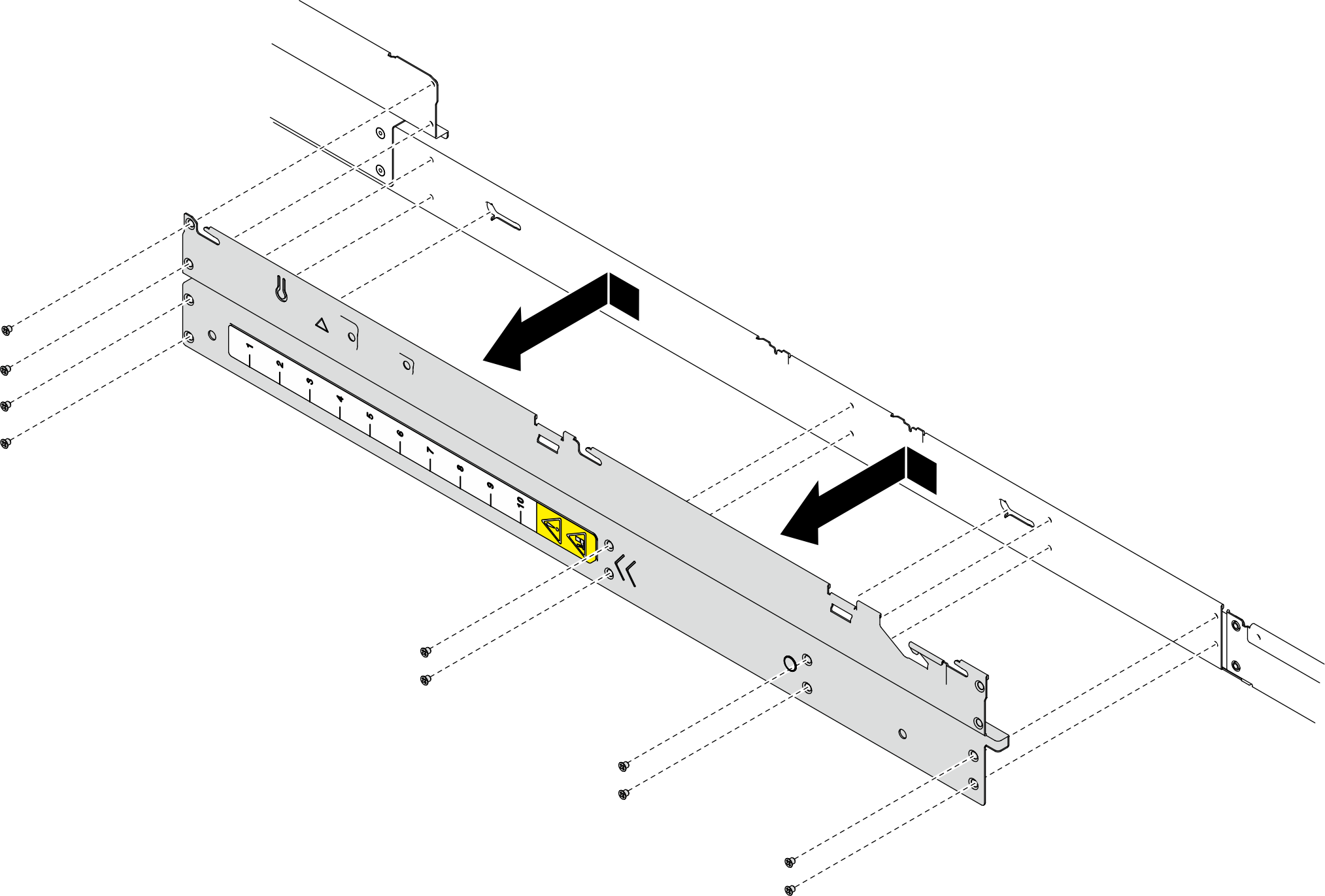
- If necessary, repeat the above steps on the right side bracket to remove it from the node.
After you finish
- Install a replacement unit (see Install a side bracket).
- If you are instructed to return the component or optional device, follow all packaging instructions, and use any packaging materials for shipping that are supplied to you.
Demo video
Give documentation feedback