Install the lower power distribution board
Use this information to install the lower power distribution board.
About this task
Attention
Read the Installation Guidelines to ensure that you work safely.
Procedure
- Place the lower power distribution board into the enclosure.
 Hold the lower power distribution board by the two standoffs located in the middle and on the left side of the board. Lower the board into the enclosure in a vertical position as illustrated.
 Rotate the front of the lower power distribution board forwards to a horizontal position with the two power bus bars pointing up. Then, align the three T-head posts with the large opening of the keyholes on the board and gently place the board into the enclosure.Figure 1. Placing the lower power distribution board into the enclosure
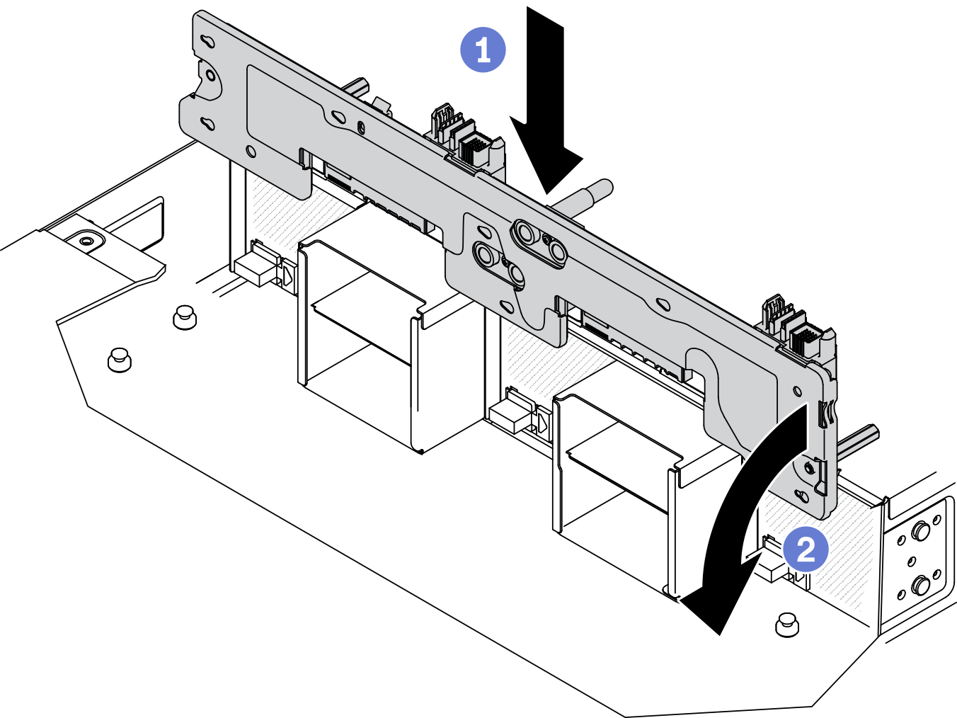
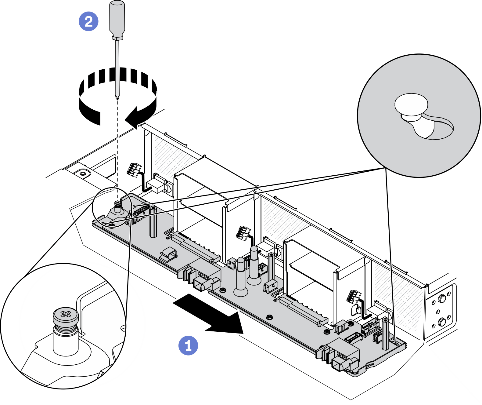
- Secure the lower power distribution board to the enclosure.
- Slide the lower power distribution board towards the right until the three T-head posts are firmly seated in the keyholes.
- Tighten the captive screw with a Phillips #1 screwdriver to secure the lower power distribution board to the enclosure.Figure 2. Securing the lower power distribution board
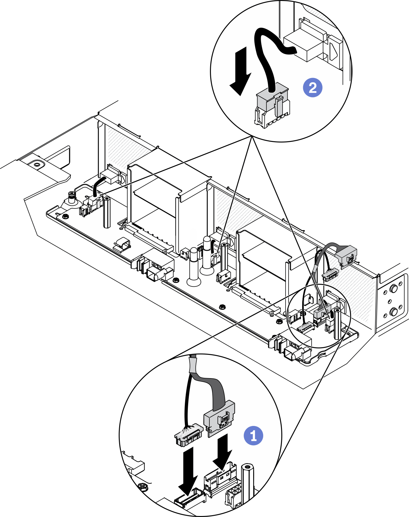
- Connect the fan cables and the interconnect cables for power distribution boards (see Power distribution boards and fan cables).
- Connect the two interconnect cables (bundled together as illustrated) to the lower power distribution board.
- Connect the three fan cables to the lower power distribution board.Figure 3. Connecting the fan cables and the interconnect cables for power distribution boards
After you finish
- Reinstall the components listed below into the enclosure in the following order:
Enclosure air baffles (see Install the enclosure air baffles).
Upper power distribution board (see Install the upper power distribution board).
Enclosure cover (see Install the enclosure cover).
Compute node(s) (see Install a compute node in the enclosure).
System Management Module 2 (see Install the hot-swap SMM2).
Power supplies (see Install a hot-swap power supply).
Install the solution back to the rack if necessary.
Reconnect power cords and all external cables.
Check the power LED on each node to make sure it changes from fast blink to slow blink to indicate the node is ready to be powered on.
Demo video
Give documentation feedback