Remove a drive
Use this information to remove a drive.
About this task
Required tools
SD650 V3 Gap pad kit
U.2 drive Conduction Plate Parts with gap pad
Read Installation Guidelines and Safety inspection checklist to ensure that you work safely.
Turn off the corresponding DWC tray that you are going to perform the task on.
Disconnect all external cables from the enclosure.
Use extra force to disconnect QSFP cables if they are connected to the solution.
Procedure
- There are different procedures for removing one and two drives, follow the steps according to your configuration.For removing one 7 mm or 15 mm drive only, complete the following steps.
 Remove the drive out of the bottom of the drive cage.
 Disconnect the cable from the drive.
Figure 1. 7 mm drive removal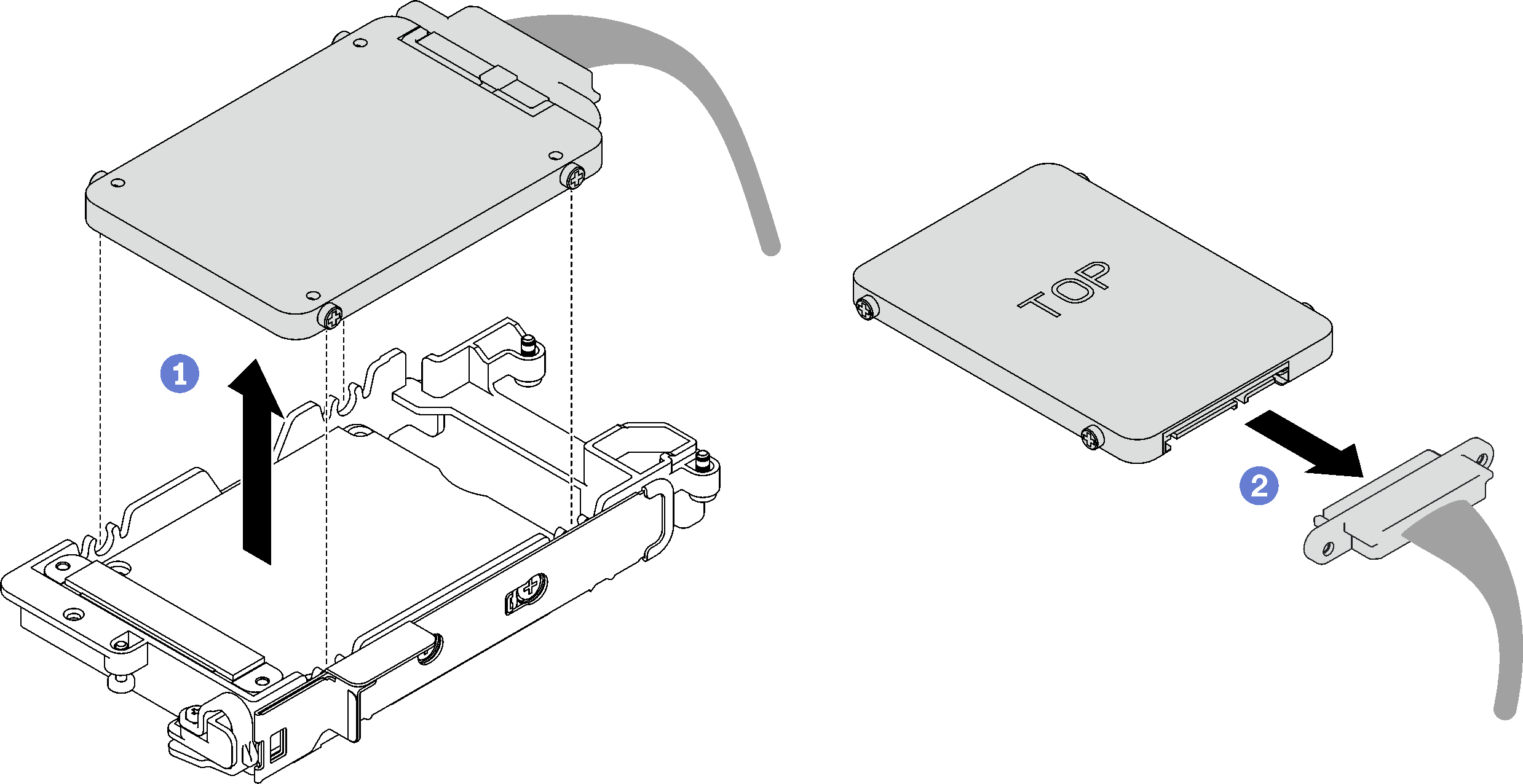 Figure 2. 15 mm drive removal
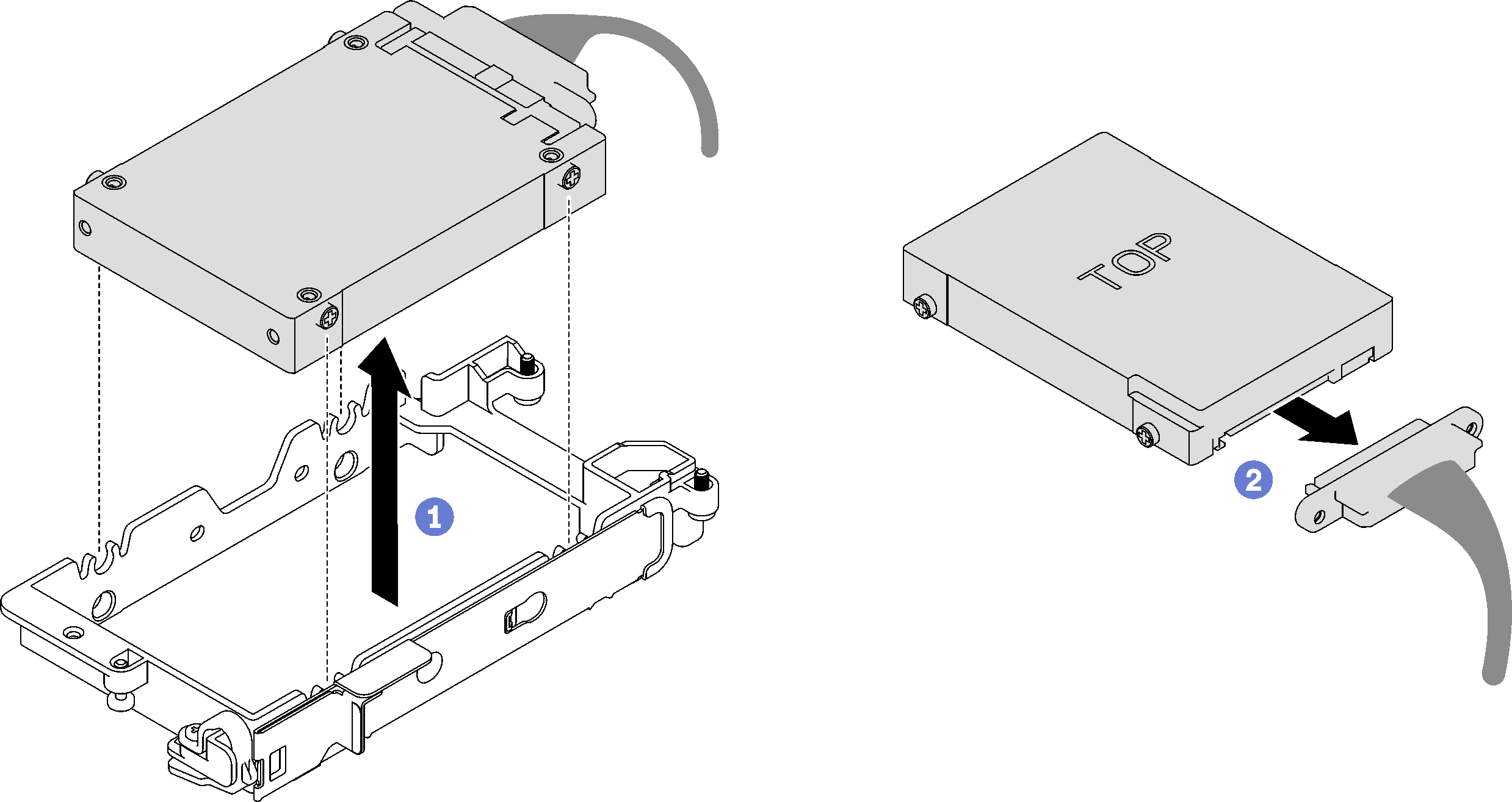 For removing two 7 mm drives, complete the following steps.
- Remove the upper drive.
- Push and hold the release latch.
- Slide the metal tab to the unlocked position.
 Pivot the drive out of the top of the drive cage as shown.
 Disconnect the cable from the drive.
Figure 3. Upper drive removal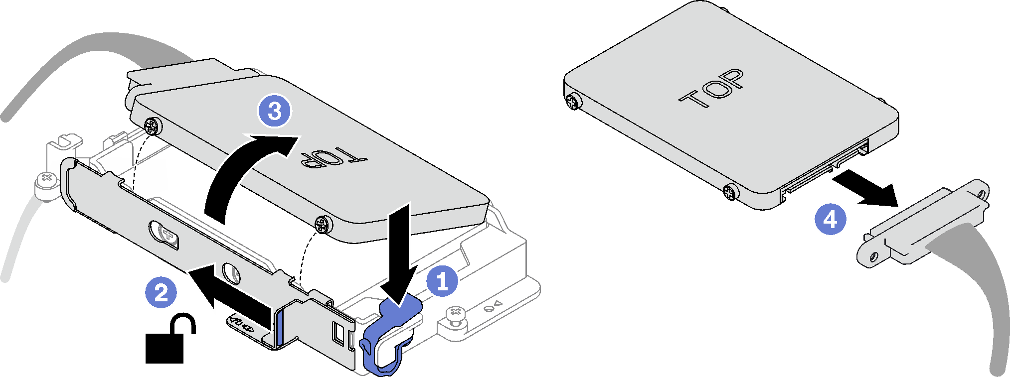
- Remove the lower drive.
- Remove the drive out of the bottom of the drive cage.
- Disconnect the cable from the drive.
Figure 4. Lower drive removal If necessary, remove the four screws securing the conduction plate and lift it out of the drive cage.
NoteMake sure the metal tab is in the unlocked position.Figure 5. Conduction plate removal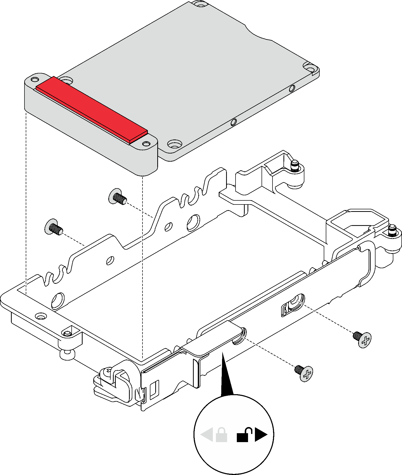
If you are instructed to return the component or optional device, follow all packaging instructions, and use any packaging materials for shipping that are supplied to you.
Demo video