Install a processor
This task has instructions for installing a processor. This task requires a Torx T30 driver.
Each processor socket must always contain a cover. When removing or installing a processor, protect empty processor sockets with a cover.
Do not touch the processor socket or processor contacts. Processor-socket contacts are very fragile and easily damaged. Contaminants on the processor contacts, such as oil from your skin, can cause connection failures.
Do not allow the thermal grease on the processor or water loop to come in contact with anything. Contact with any surface can compromise the thermal grease, rendering it ineffective. Thermal grease can damage components, such as electrical connectors in the processor socket. Do not remove the grease cover from the cold plate until you are instructed to do so.
To avoid damaging the water loop, always use the water loop carrier when removing, installing or folding the water loop.
To ensure the best performance, check the manufacturing date on the new heat sink and make sure it does not exceed 2 years. Otherwise, wipe off the existing thermal grease and apply the new grease onto it for optimal thermal performance.
Processors are keyed for the socket where they can be installed and for their orientation in the socket.
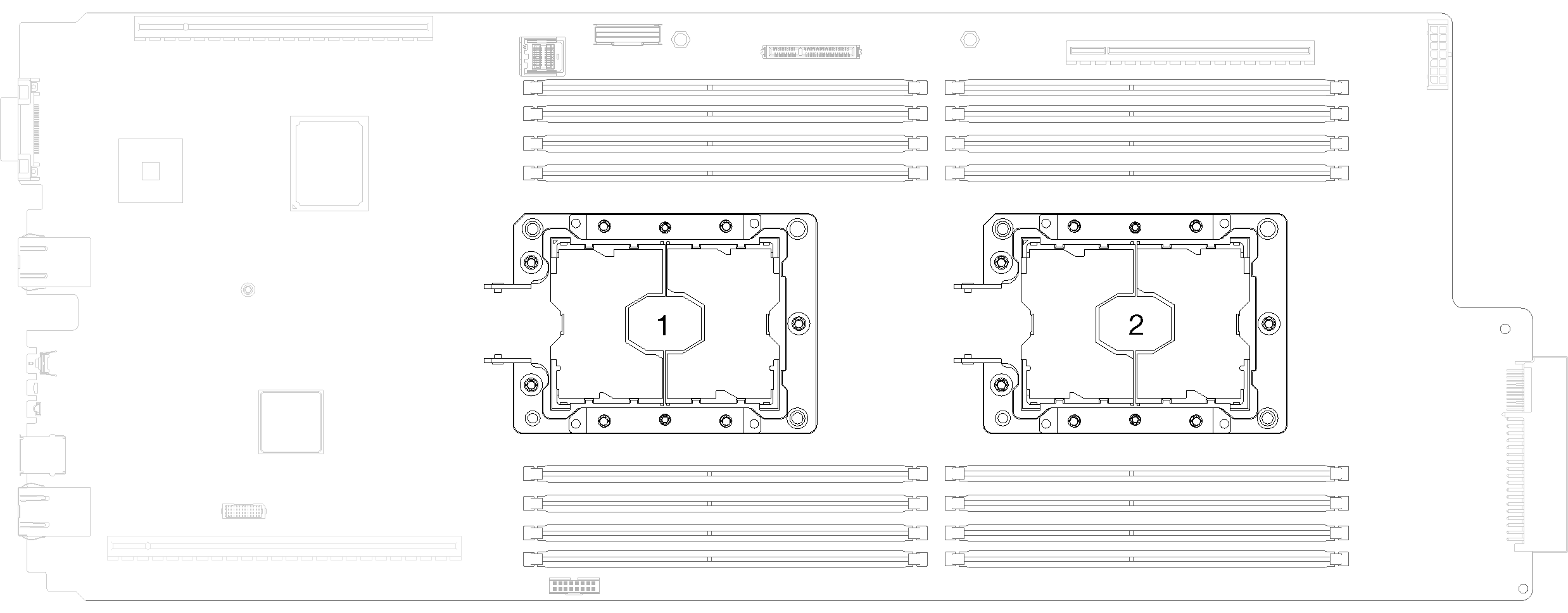
See Lenovo ServerProven website for a list of processors supported for your system. All processors on the system board must have the same speed, number of cores, and frequency.
Before you install a new or replace a processor, update your system firmware to the latest level. See Update the firmware.
Optional devices available for your system might have specific processor requirements. See the documentation that comes with the optional device for information.
Read the Installation Guidelines to ensure that you work safely.
Remove the existing processor, if one is installed. See Remove a processor.
NoteReplacement processors come with both rectangular and square processor retainers. A rectangular retainer comes attached to the processor. The square retainer can be discarded as it doesn't fit on the underside of the water loop cold plates.If you are replacing a processor, replace the processor retainer. Processor retainers should not be reused once they have been pried away from water loop cold plates..
Remove the old processor retainer.
NoteRetainer removal is slightly different for Internal Faceplate Transition (IFT) Carrier and non-IFT processors.Figure 1. Removing a non-IFT processor retainer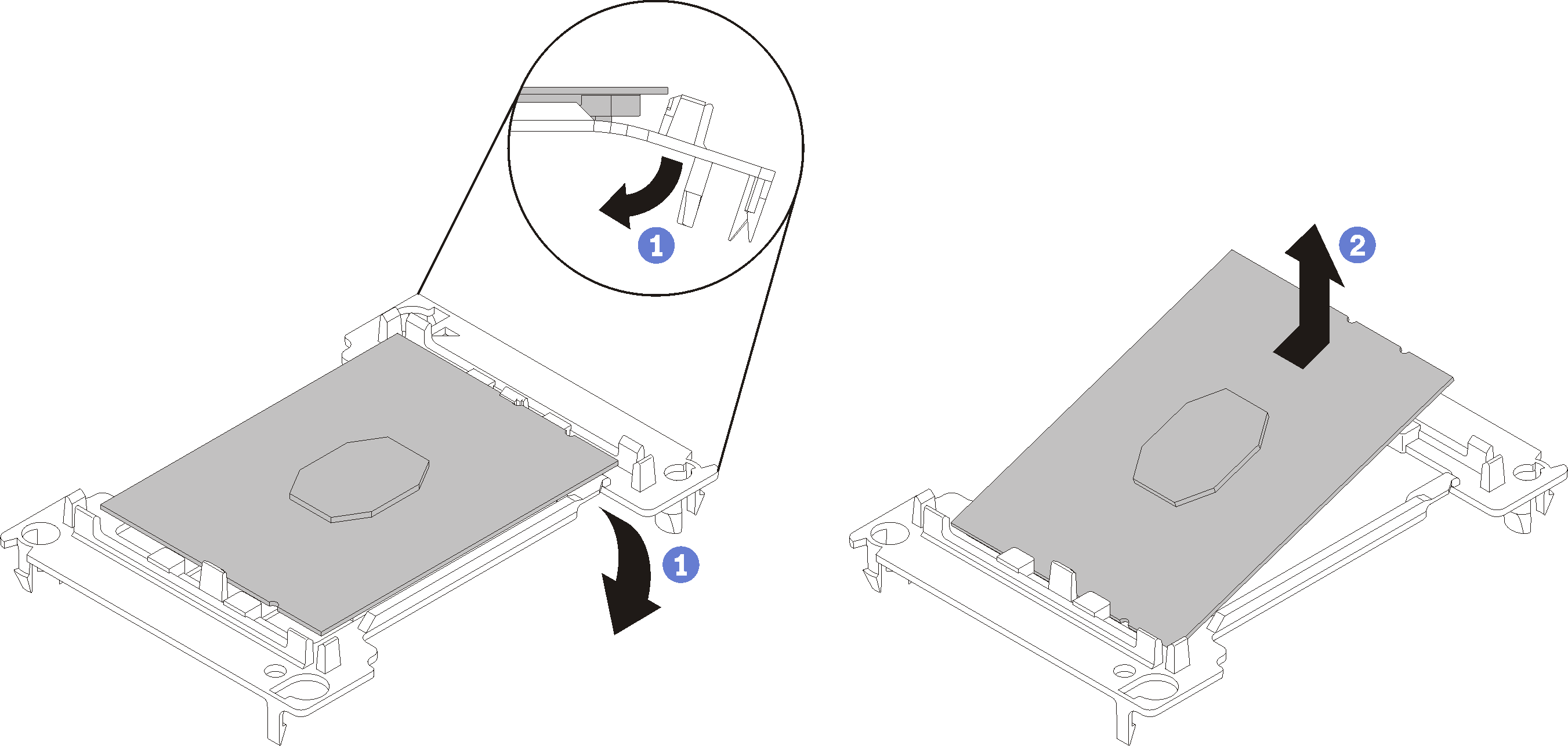 Figure 2. Removing an IFT processor retainer
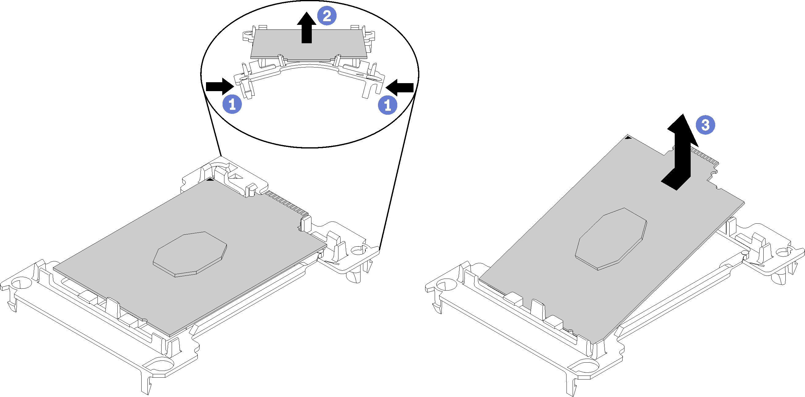 NoteWhen the processor is out of its retainer, hold the processor by the long edges to prevent touching the contacts or the thermal grease, if it is applied.
With the processor-contact side of the non-IFT processor up, flex the ends of the retainer down and away from the processor to release the retaining clips; then, remove the processor from the retainer. Discard the old retainer.
Install the processor into the new processor retainer.
NoteRetainer installation is slightly different for non-IFT and IFT processors.Figure 3. Installing a non-IFT processor retainer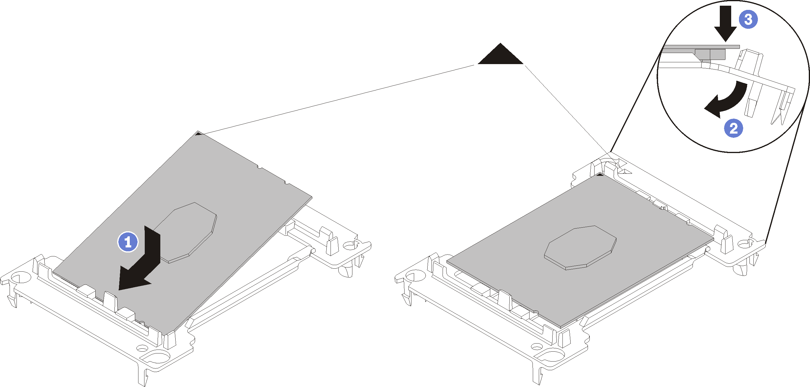 Figure 4. Installing an IFT processor retainer
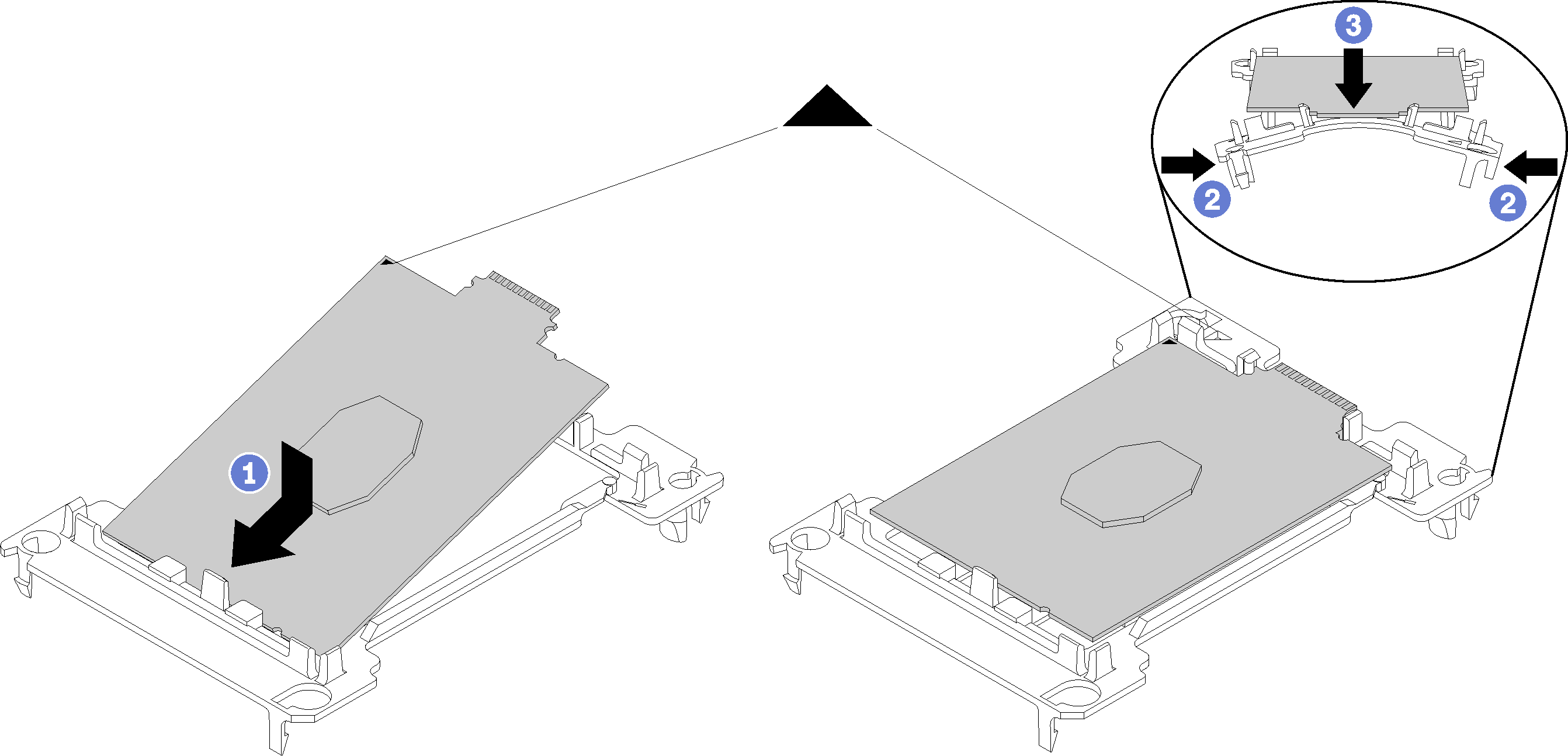
Position the processor on the new retainer so that the triangular marks align; then, insert the unmarked end of the processor into the retainer.
Holding the inserted end of the non-IFT processor in place, flex the opposite end of the retainer down and away from the processor until you can press the processor under the clip on the retainer.
To prevent the processor from falling out of the retainer after it is inserted, keep the processor-contact side up and hold the processor-retainer assembly by the sides of the retainer.
If there is any old thermal grease on the processor, gently clean the top of the processor using an alcohol cleaning pad.
NoteIf you are applying new thermal grease on the top of the processor, make sure to do it after the alcohol has fully evaporated.
If you are replacing a processor:
Remove the processor identification label from the water loop and replace it with the new label that comes with the replacement processor.
To ensure the best performance, check the manufacturing date on the new heat sink and make sure it does not exceed 2 years. Otherwise, wipe off the existing thermal grease and apply the new grease onto it for optimal thermal performance.
Apply new thermal grease (0.65 g) to the top of the new processor. If you have cleaned the top of the processor with an alcohol cleaning pad, make sure to apply the new thermal grease after the alcohol has fully evaporated.
Figure 5. Thermal grease application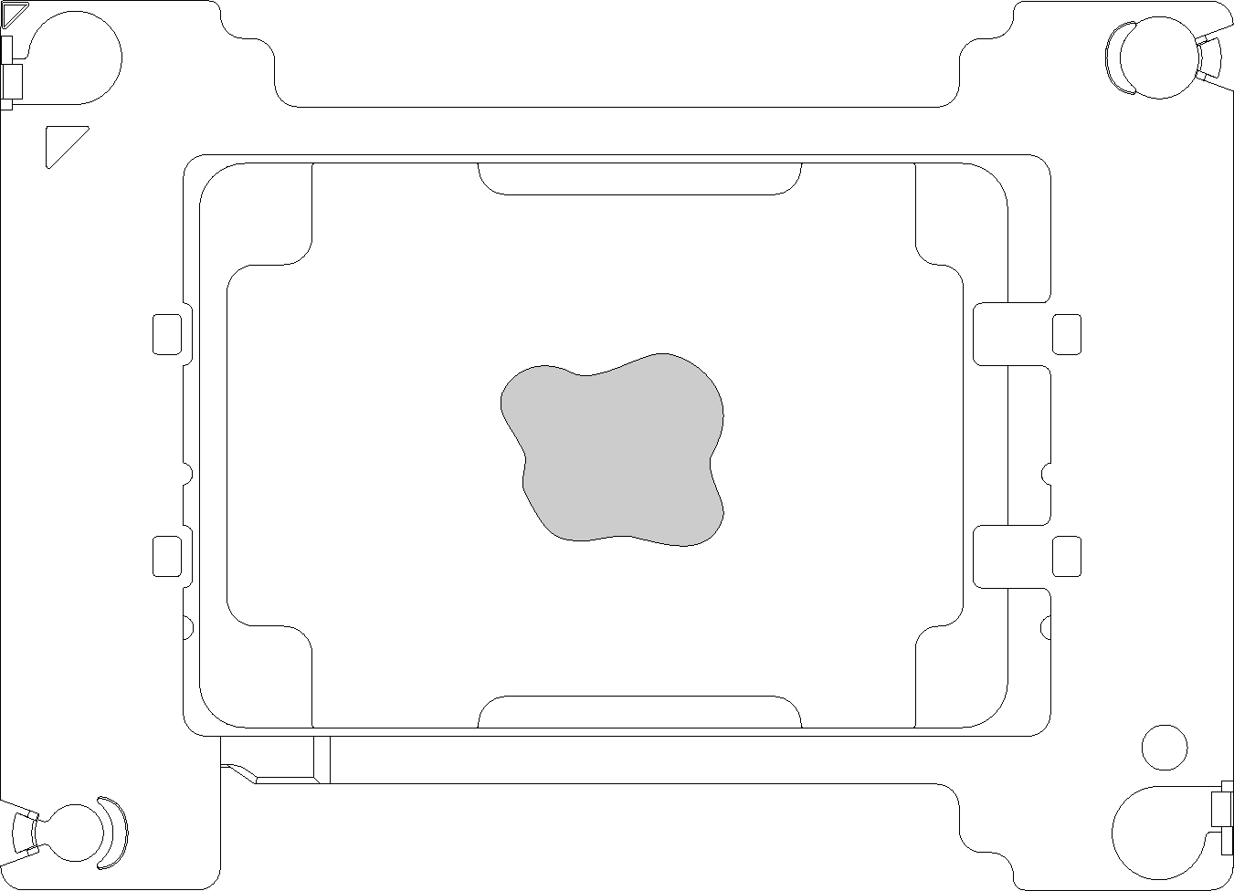
Carefully place the processor and retainer on a flat surface with the processor-contact side down.
Apply approximately 0.65 g of thermal grease to the center of the processor top.
If you are replacing the water loop, remove the processor identification label from the old water loop and place it on the new water loop in the same location.
If you are unable to remove the label and place it on the new water loop, or if the label is damaged during transfer, write the processor serial number from the processor identification label on the new water loop in the same location as the label would be placed using a permanent marker.
Complete the following steps to install a processor.
- Install processors to underside of water loop cold plates.Figure 7. Installing a processor
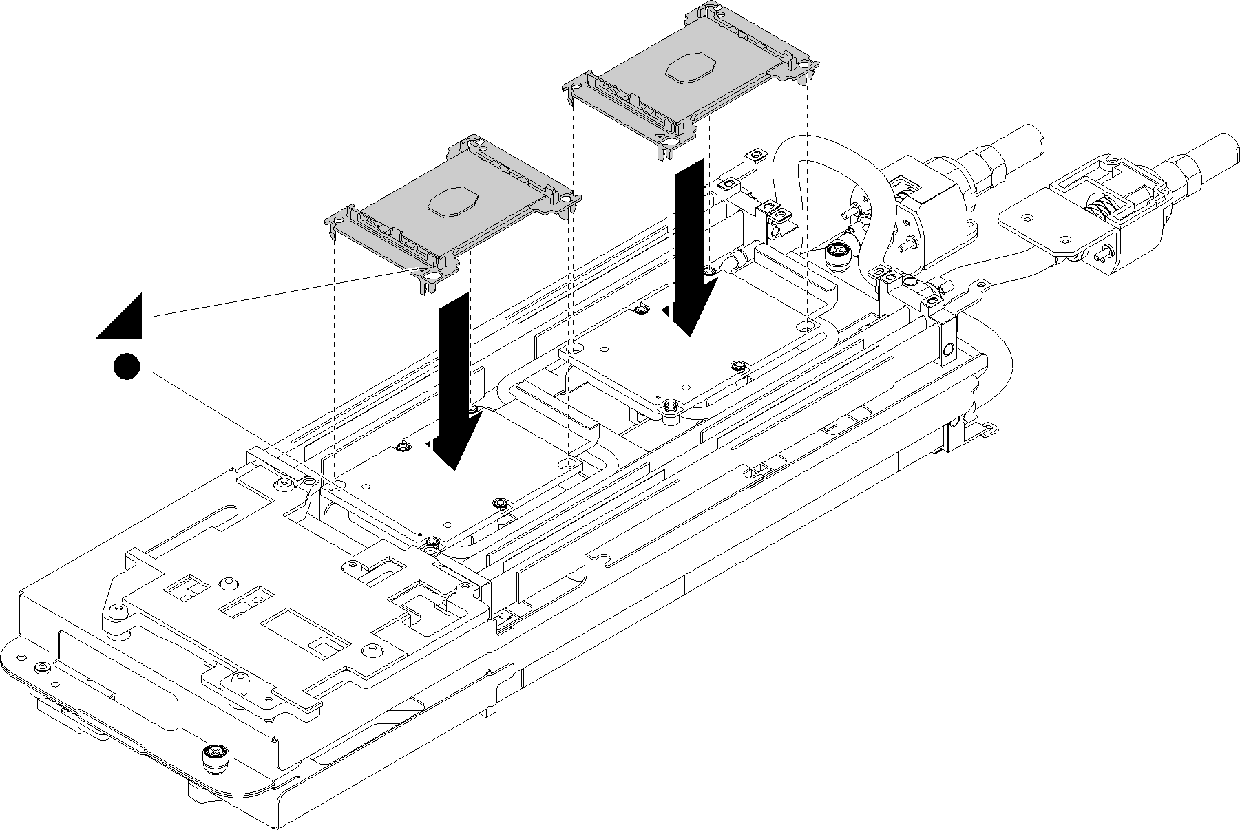
- Align the triangular mark on the processor retainer with the guide hole on the underside of the water loop cold plate; then, attach the processor to the underside of the water loop cold plate by inserting the processor retainer posts and clips features into the openings at the four corners of the cold plate.
- Remove the processor socket cover, if one is installed on the processor socket, by placing your fingers in the half-circles at each end of the cover and lifting it from the cold plate.
- If the processor has an IFT connector, make sure that the IFT cable is correctly routed and connected. See Internal cable routing.
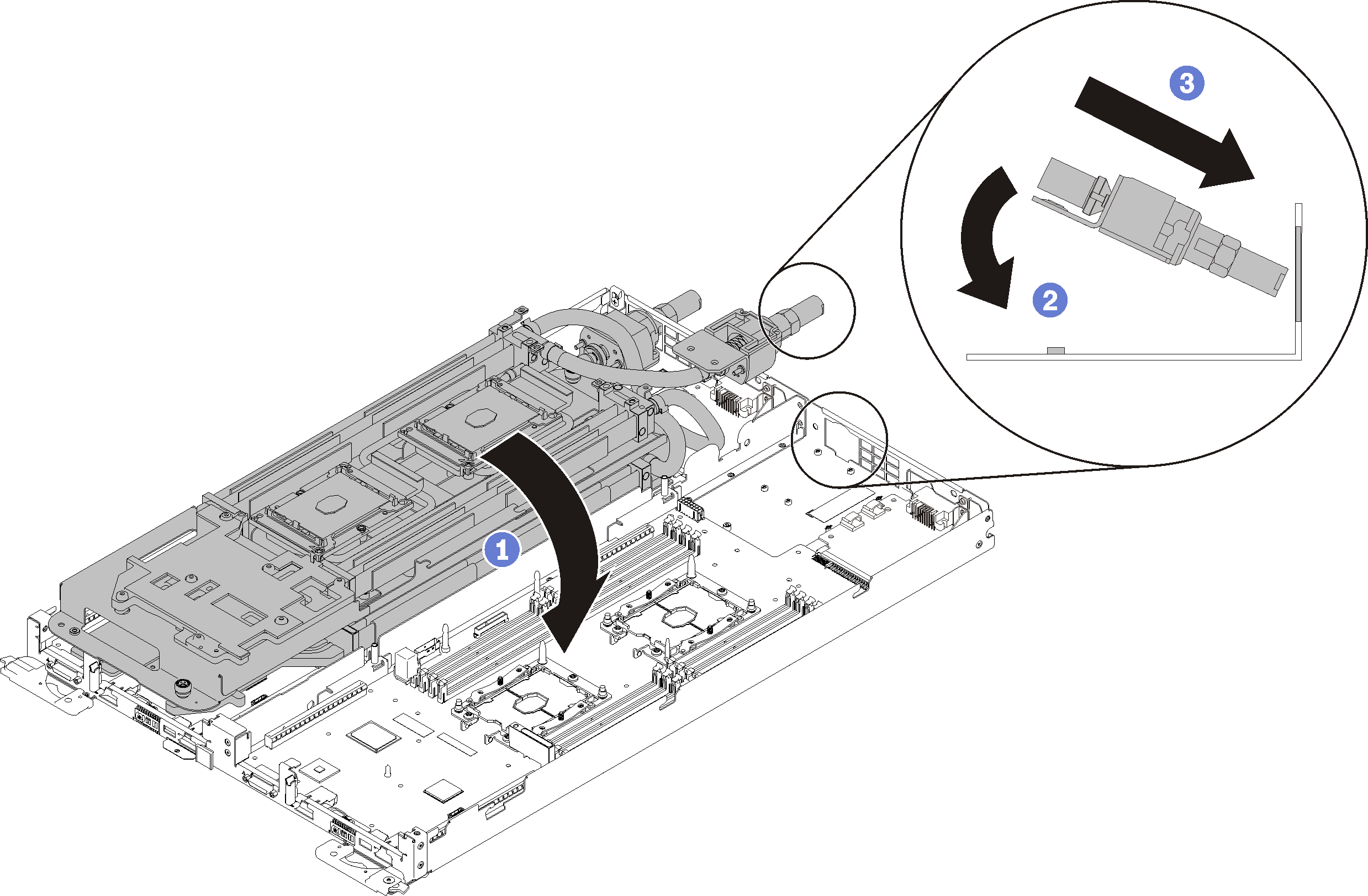
- Fold the water loop.
- Gently put the other side of the water loop down and ensure it is seated firmly on the system board.Figure 8. Water loop installation
- Secure the water loop and the quick connect to the tray by carefully inserting 15 silver Torx T10 screws.Figure 9. Silver T10 screw installation
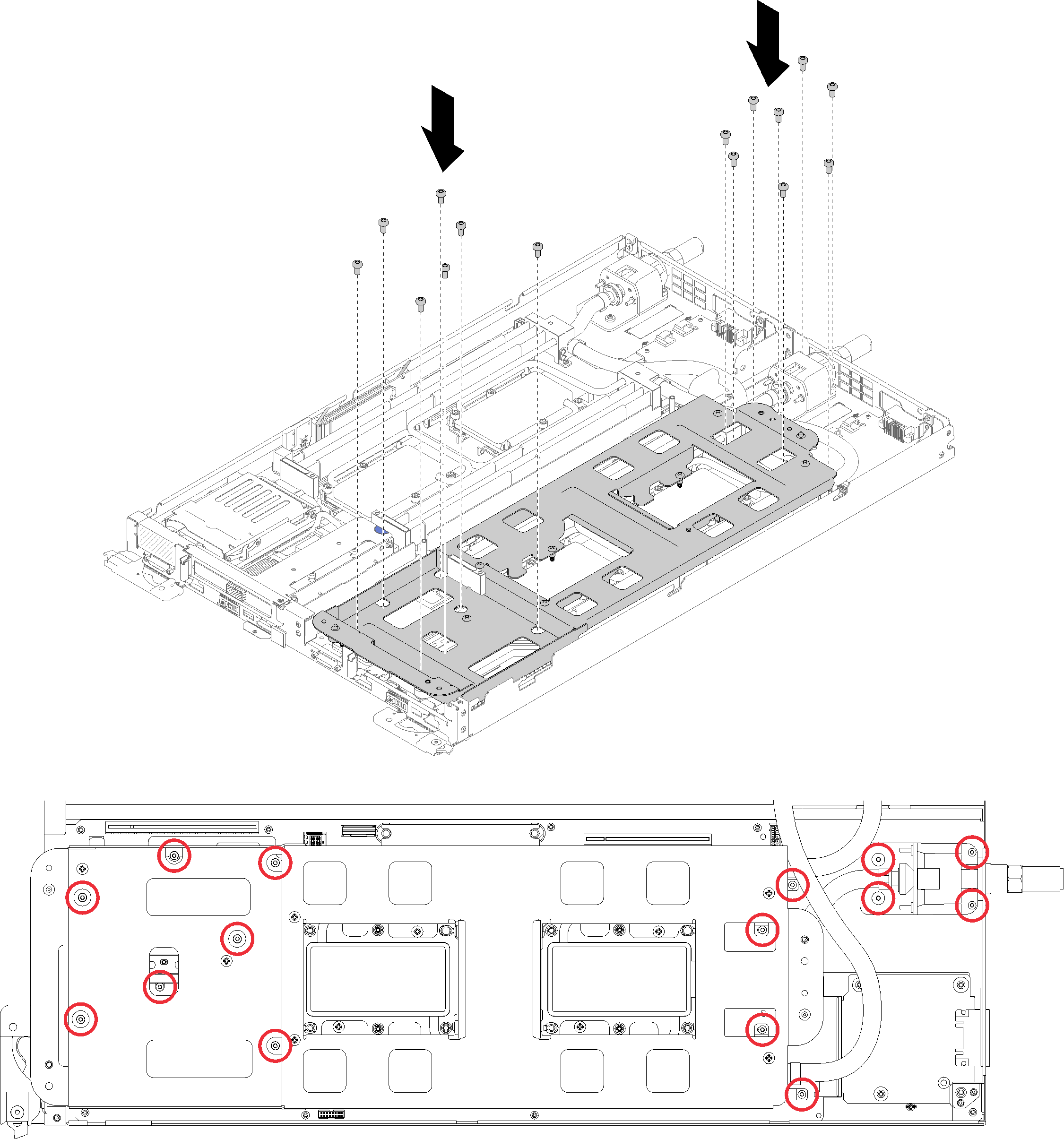
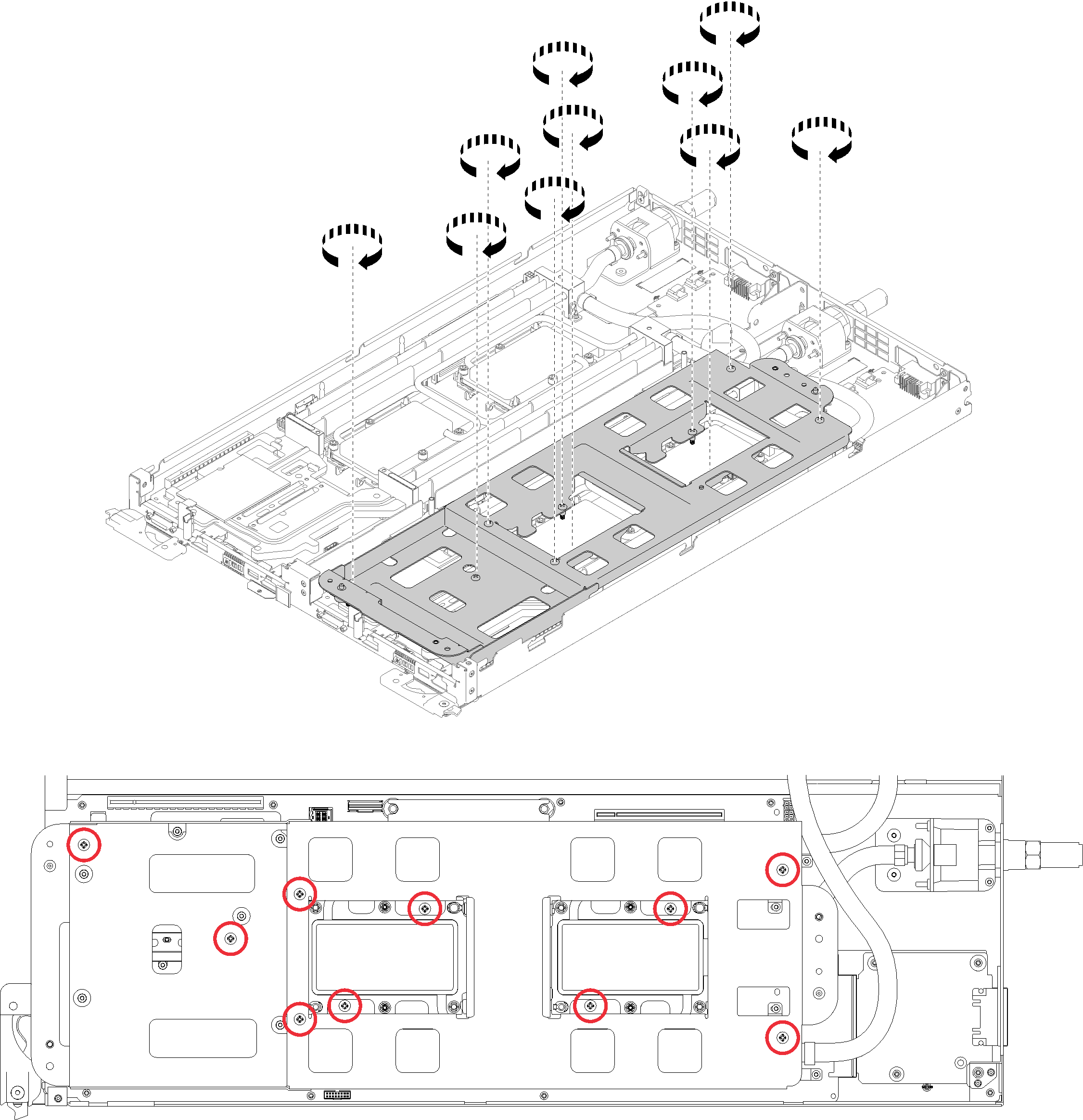
- Loosen water loop carrier screws (10x P2 screws per node).Figure 10. Loosening captive P2 screws
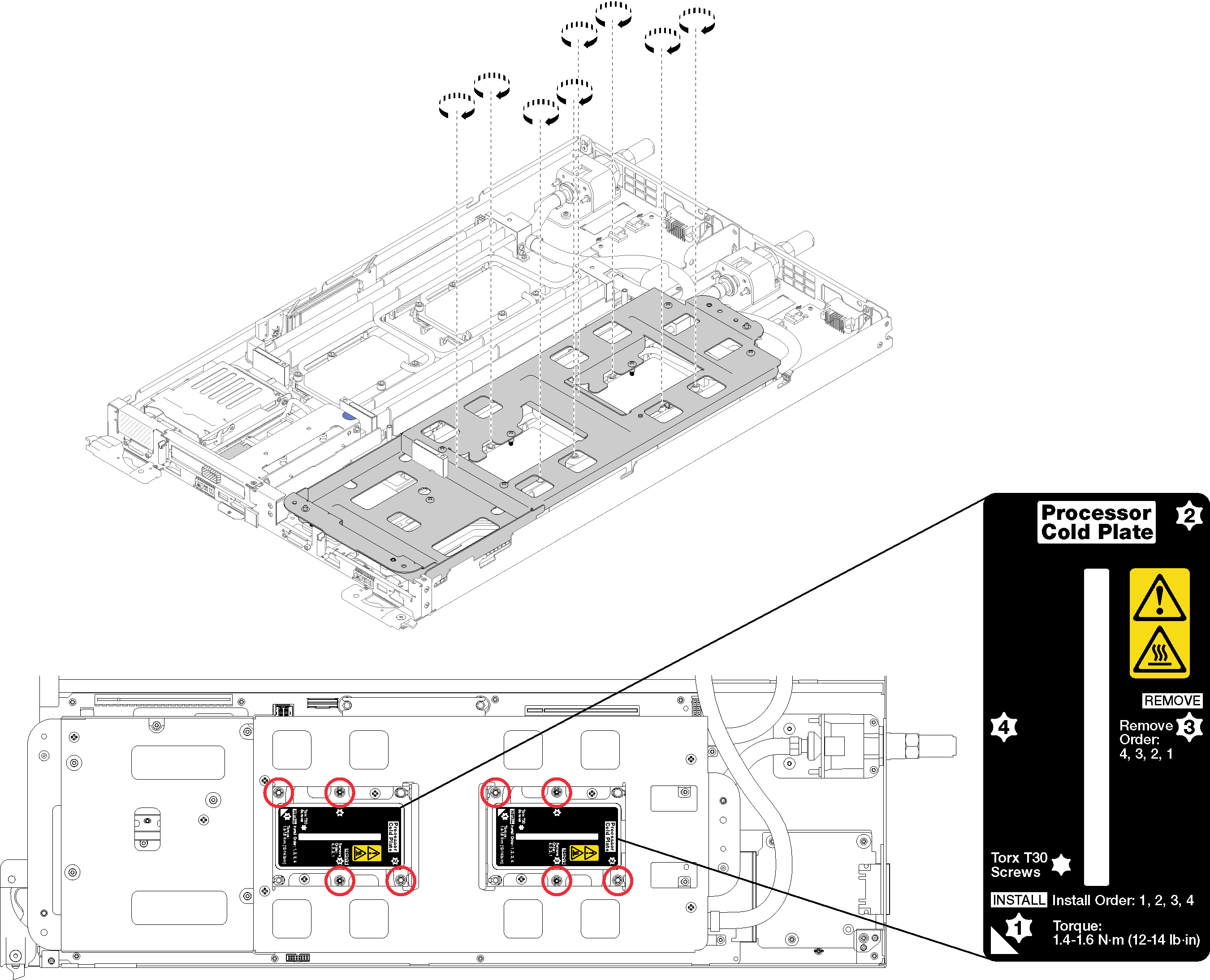
- Fully tighten the Torx T30 captive fasteners in the installation sequence shown on the label. Tighten the screws until they stop. (For reference, the torque required for the nuts to fully tighten is 1.4 — 1.6 newton-meters, 12 — 14 inch-pounds).AttentionTo prevent damage to components, make sure that you follow the indicated tightening sequence.Figure 11. Tightening screws
- Gently put the other side of the water loop down and ensure it is seated firmly on the system board.
After you install a processor:
Carefully lift the water loop carrier up and away from the water loop.
Figure 12. Water loop carrier removal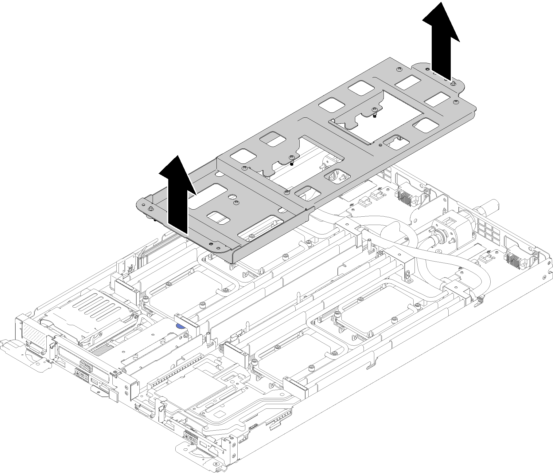
Reinstall all four DIMM covers and DIMMs for both nodes (see Install a DIMM).
Reinstall M.2 backplanes for both nodes (see Install the M.2 backplane).
Reinstall drive cage assemblies if applicable (see Install a drive cage assembly).
Reinstall PCIe rise assemblies if applicable (see Install an adapter or Install an Internal Faceplate Transition (IFT) adapterdepending on your configuration).
Reinstall both air baffles.
Figure 13. Air baffle installation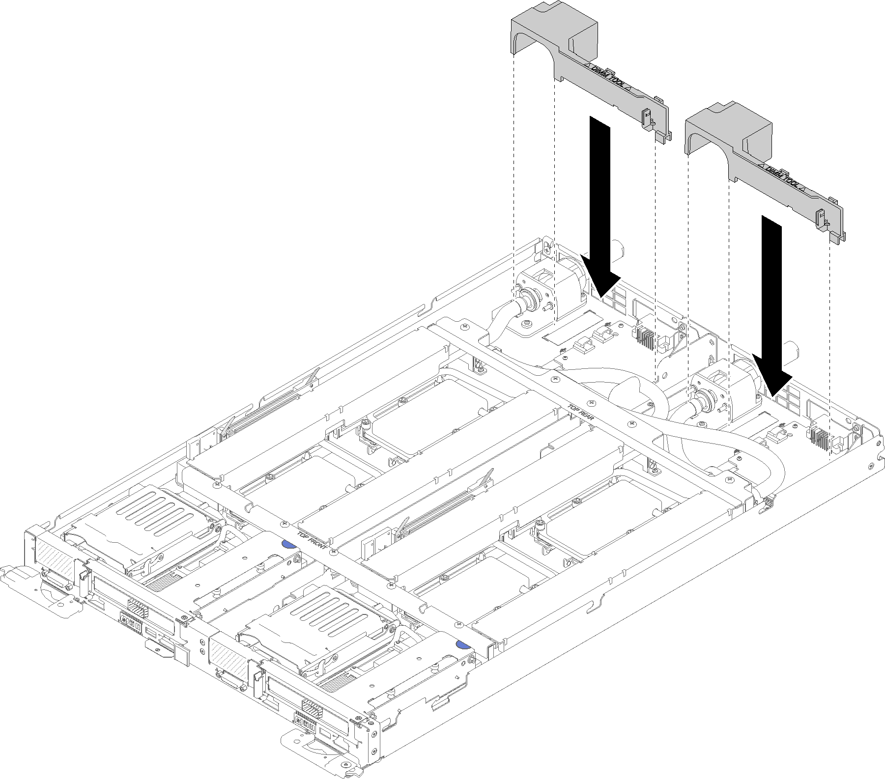
Reinstall the front and the rear cross braces (10x P2 screws).
Figure 14. Cross brace installation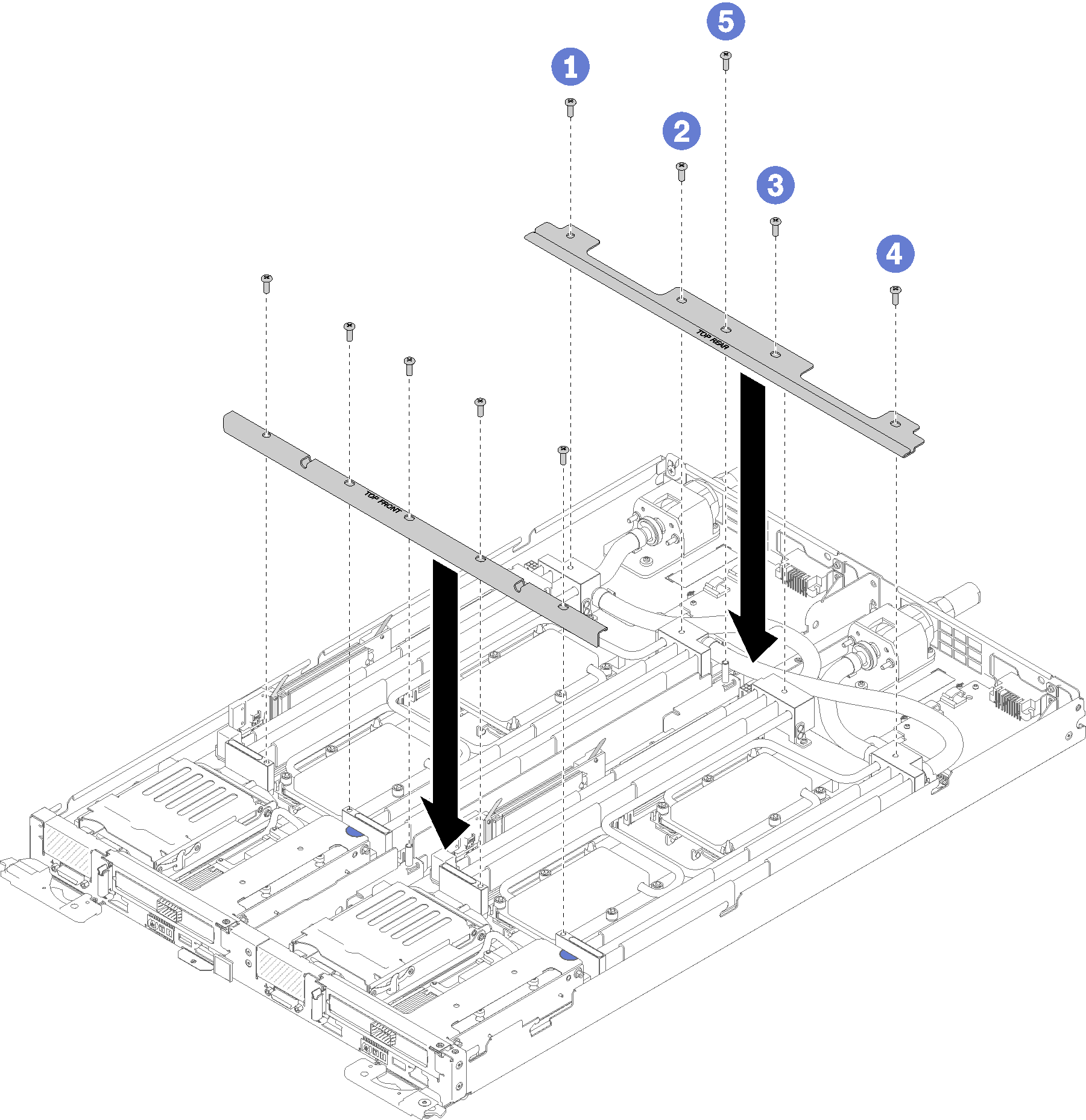
Reinstall the tray cover (see Install the tray cover).
Reinstall the tray (see Install a DWC tray in the enclosure).
Check the power LED on each node to make sure it changes from fast blink to slow blink to indicate both nodes are ready to be powered on.
Demo video