Remove a processor
This task has instructions for removing an assembled processor. This task requires a Torx T30 driver.
Each processor socket must always contain a cover. When removing or installing a processor, protect empty processor sockets with a cover.
Do not touch the processor socket or processor contacts. Processor-socket contacts are very fragile and easily damaged. Contaminants on the processor contacts, such as oil from your skin, can cause connection failures.
Do not allow the thermal grease on the processor or water loop to come in contact with anything. Contact with any surface can compromise the thermal grease, rendering it ineffective. Thermal grease can damage components, such as electrical connectors in the processor socket. Do not remove the grease cover from the cold plate until you are instructed to do so.
To avoid damaging the water loop, always use the water loop carrier when removing, installing or folding the water loop.
To ensure the best performance, check the manufacturing date on the new heat sink and make sure it does not exceed 2 years. Otherwise, wipe off the existing thermal grease and apply the new grease onto it for optimal thermal performance.
Read the Installation Guidelines to ensure that you work safely.
Turn off the corresponding DWC tray that you are going to perform the task on.
Remove the tray (see Remove a DWC tray from the enclosure).
Remove the tray cover (see Remove the tray cover).
Remove both air baffles.
Figure 1. Air baffle removal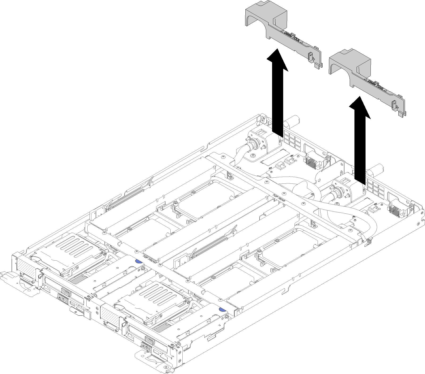
Remove the front and the rear cross braces (10x P2 screws).
Figure 2. Cross brace removal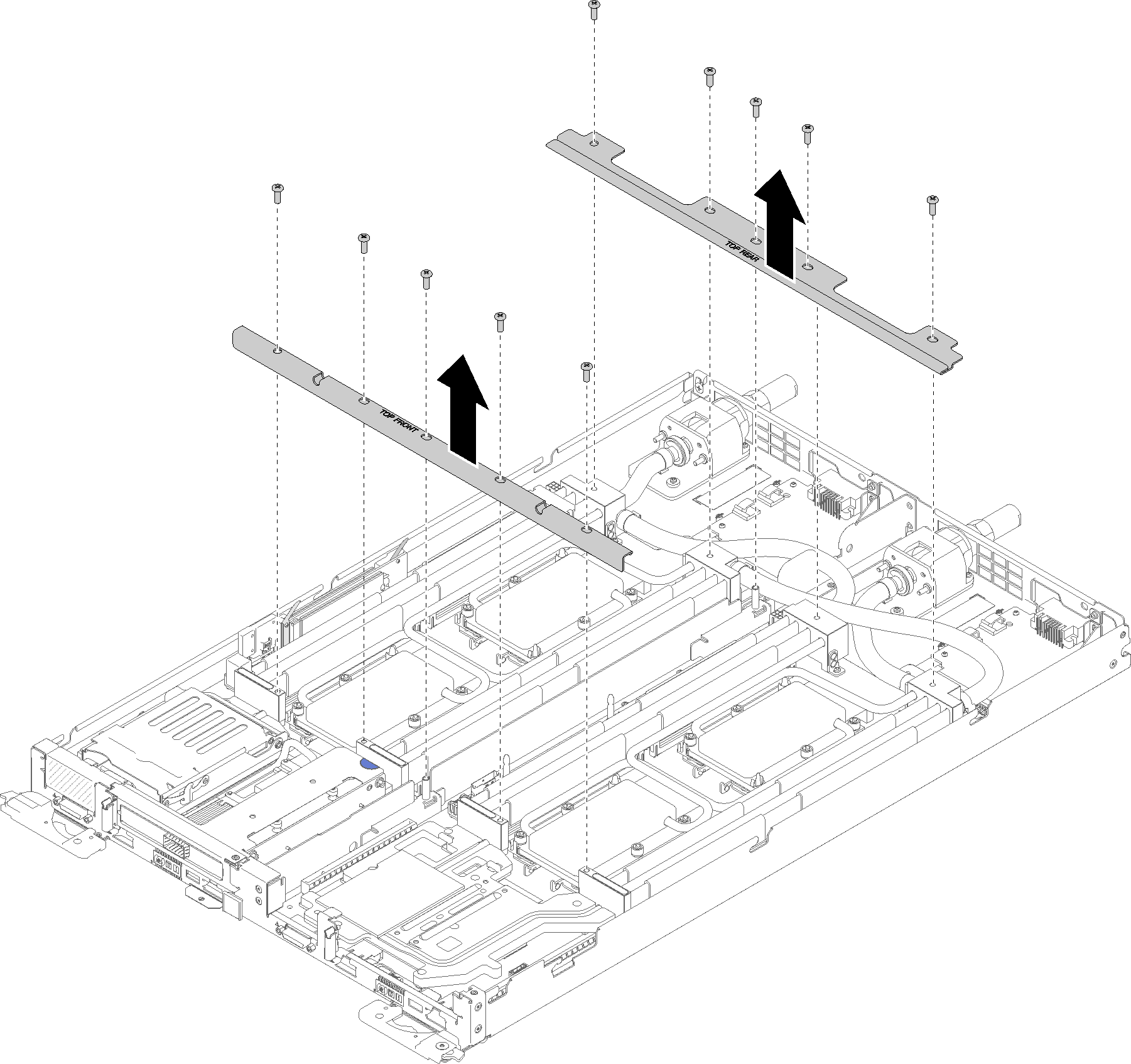
Remove all four DIMM covers and DIMMs for both nodes (see Remove a DIMM).
Remove M.2 Backplanes from both nodes (see Remove the M.2 backplane).
Remove drive cage assemblies from the node (see Remove a drive cage assembly).
Remove PCIe riser assemblies from the node if applicable (see Remove an adapter or Remove an Internal Faceplate Transition (IFT) adapter depending on your configuration).
Fold the water loop.
Orient the water loop carrier with two M.2 backplane guide pins; then, gently put the water loop carrier down and ensure it is seated firmly on the water loop.
Figure 3. Water loop carrier installation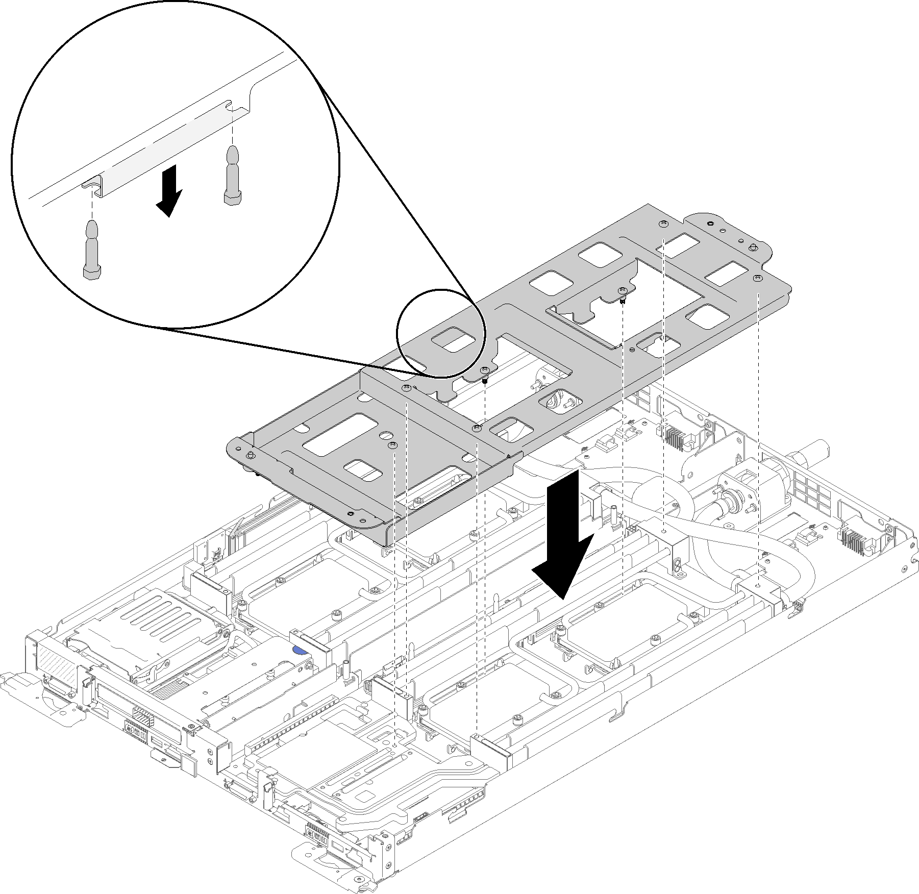
Remove water loop screws (15x silver Torx T10 screws per node).
Figure 4. Silver T10 screw removal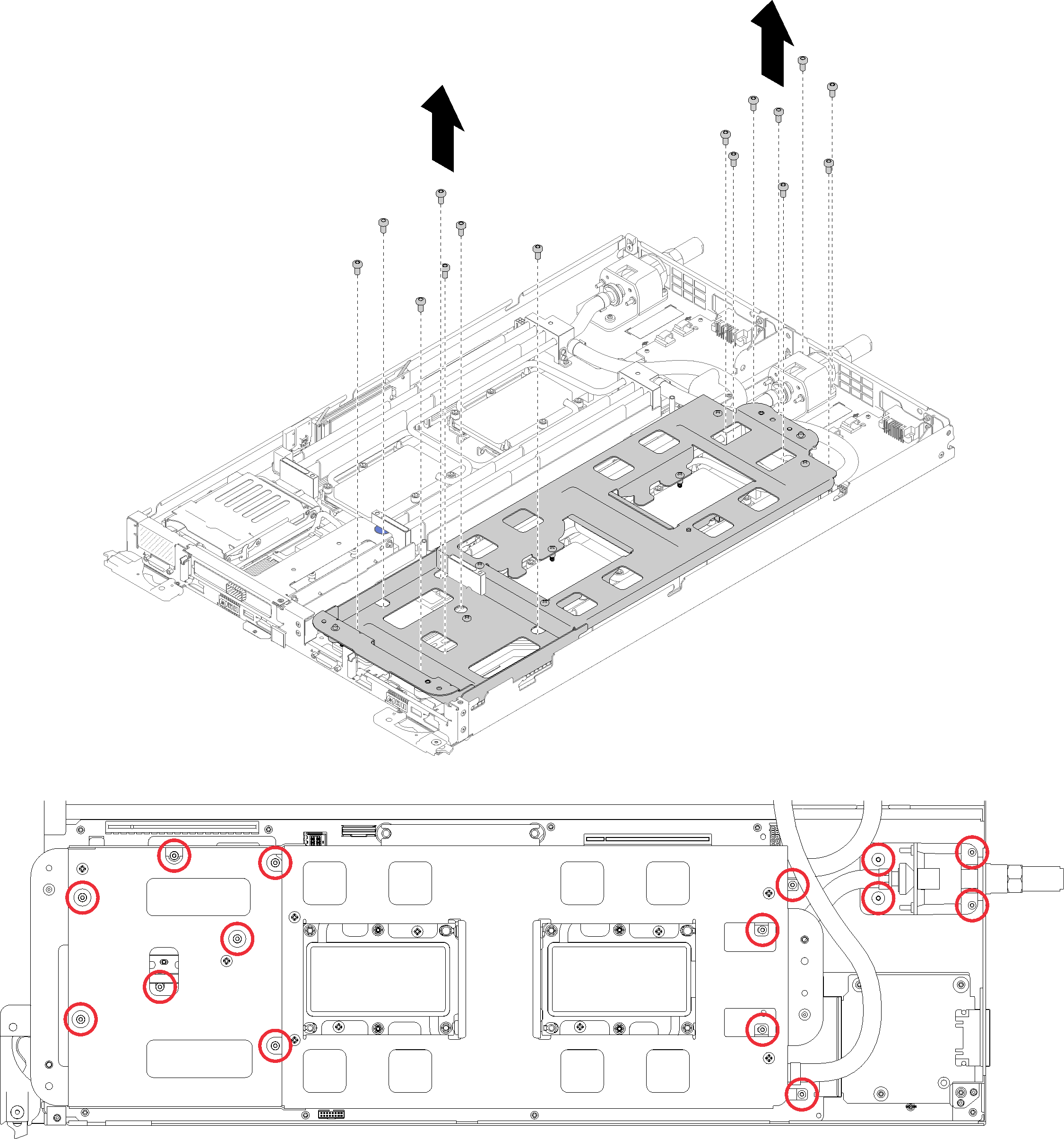
Fully loosen all Torx T30 captive fasteners (8x Torx T30 captive fasteners per node) on cold plates in the removal sequence shown on the cold plate label.
AttentionTo prevent damage to components, make sure that you follow the indicated loosening sequence.Figure 5. Loosening Torx T30 captive fasteners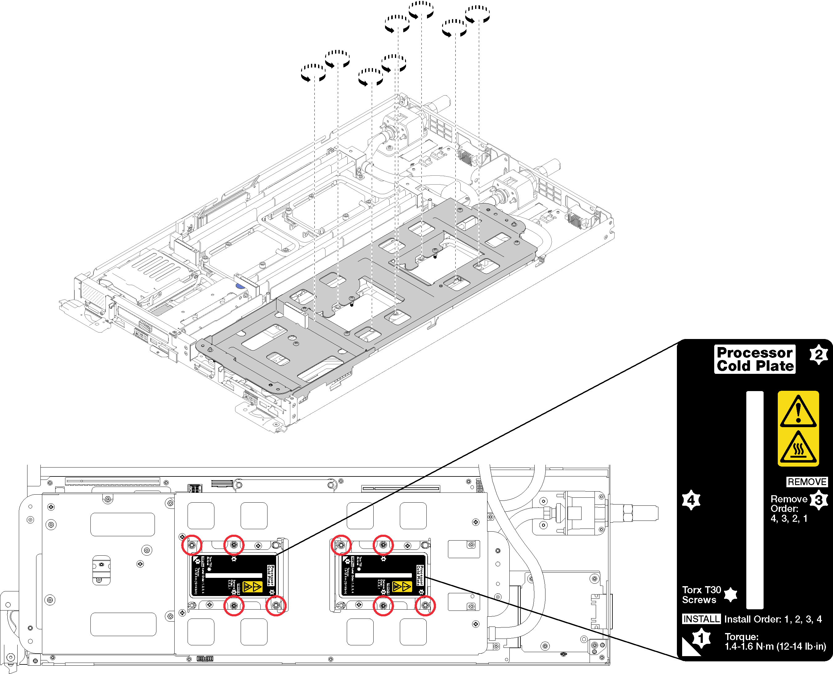
Tighten water loop carrier screws (10x P2 screws per node).
Figure 6. Tightening captive P2 screws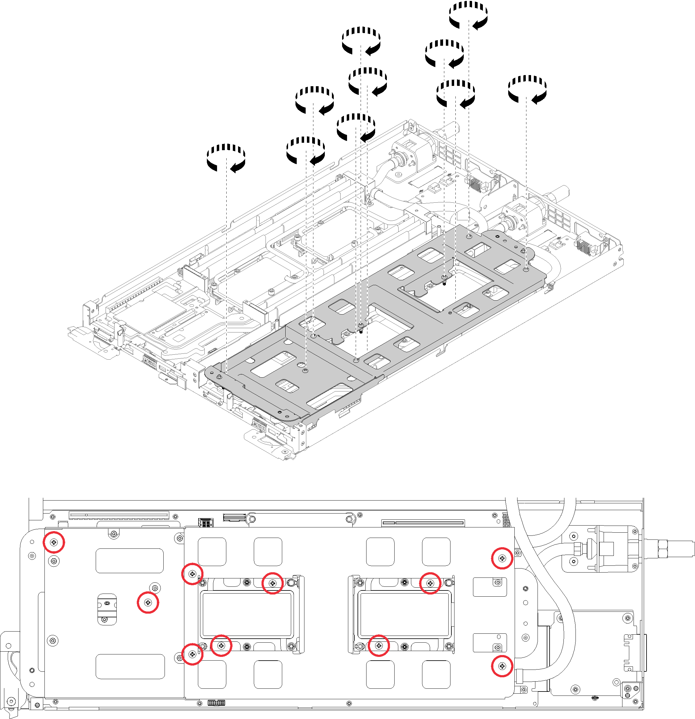
- Fold the water loop.
Carefully lift the water loop up off the system board, then unhook the quick connect from the four alignment posts and slide the quick connect out of the opening in the rear of the tray.
Carefully rotate the water loop so one half is sitting on top of the other half.
Figure 7. Folding the water loop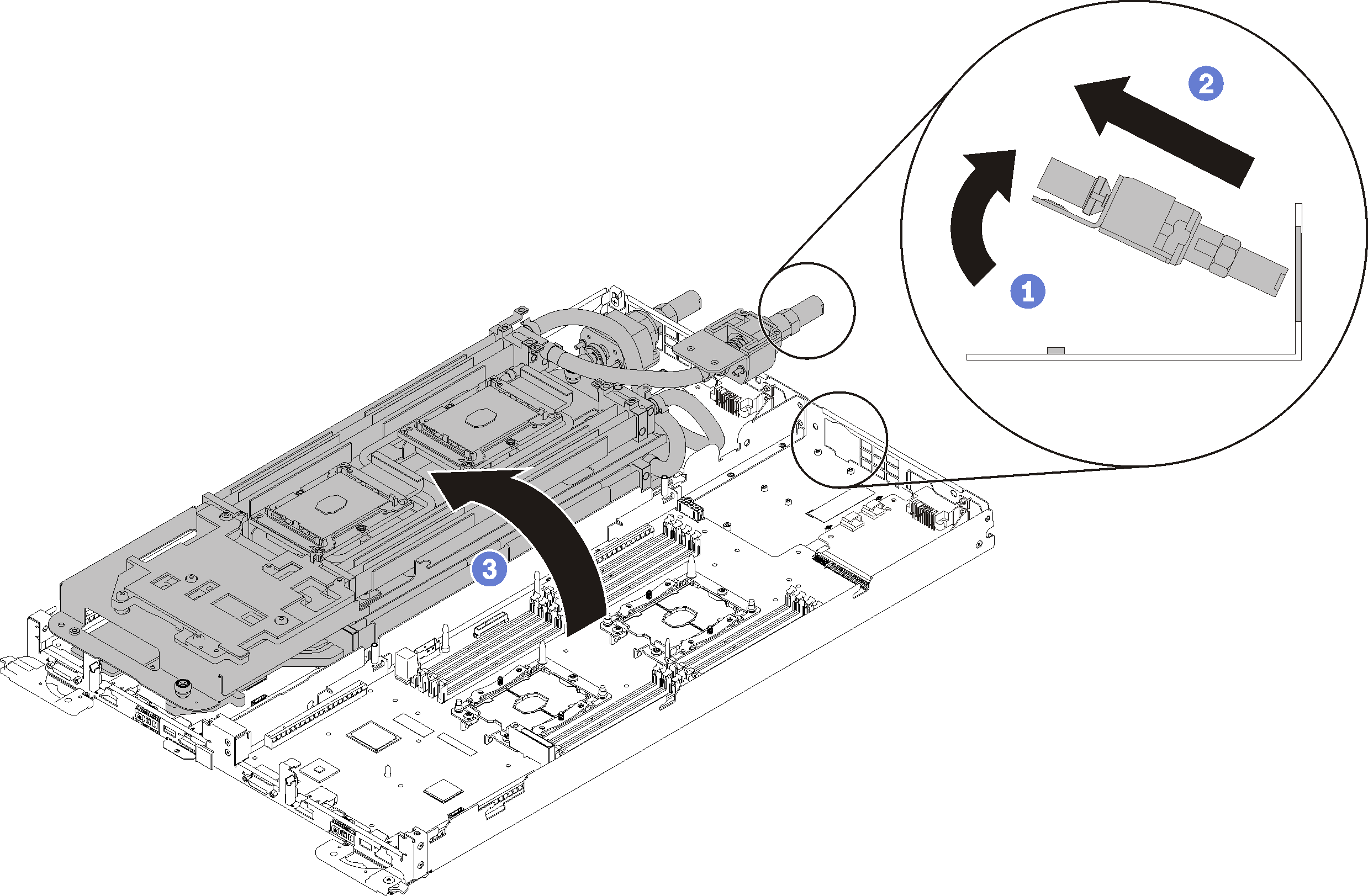
Complete the following steps to remove a processor.
- If the processor has an Internal Faceplate Transition (IFT) Carrier connector, disconnect the cable.
Rotate the IFT connector release spring up and away from the cable side of the connector; then, disconnect the IFT connector.
Figure 8. Screws and retaining clamp removal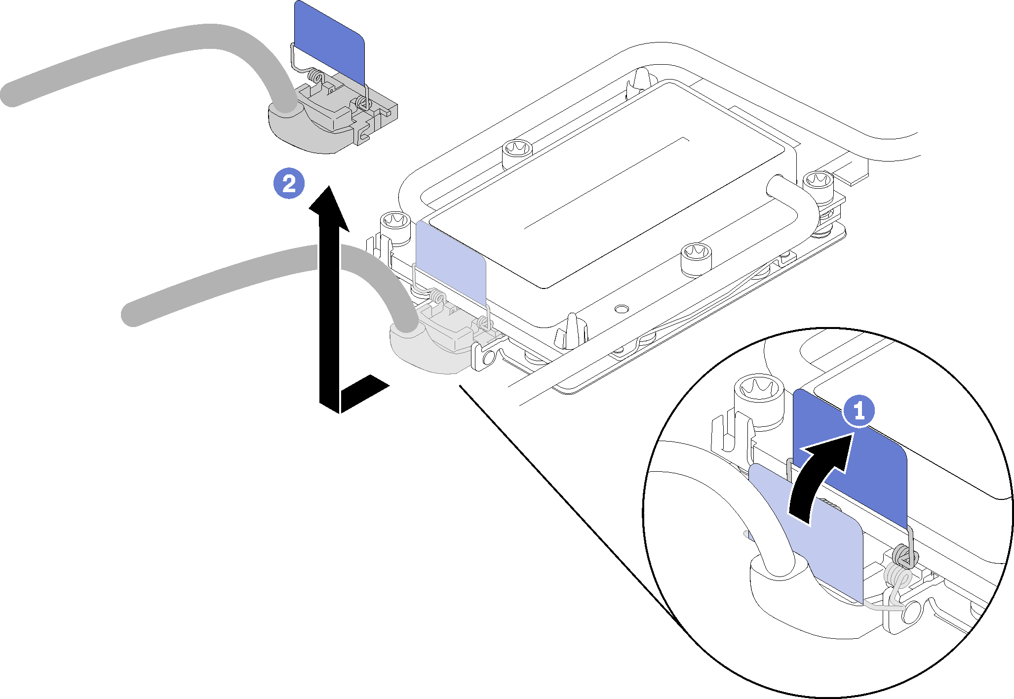
- Remove the processor from the underside of the cold plate.
If you are replacing the processor, separate the processor from its retainer.
Press the retaining clip at the corner of the processor retainer closest to the pry point; then, gently pry this corner of the retainer away from the heat sink with a flat-bladed screwdriver, using a twisting motion to break the processor-to-cold-plate seal.
Release the remaining retaining clips and lift the processor retainer from the underside of the cold plate.
After separating the processor and retainer from the cold plate, hold the processor and retainer with the thermal-grease side down and the processor-contact side up to prevent the processor from falling out of the retainer.
NoteThe processor retainer will be removed and discarded in a later step and replaced with a new one.Figure 9. Remove processor and processor retainer from underside of cold plate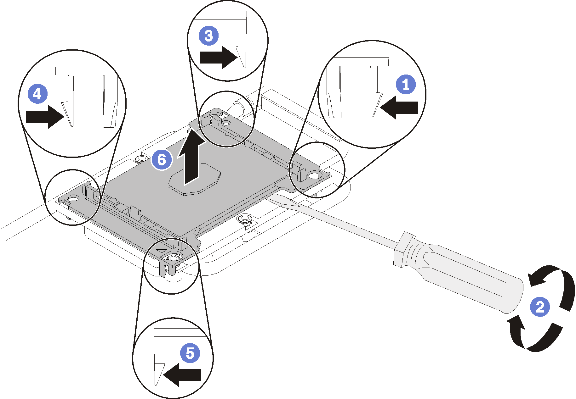
If you are replacing the processor, you will be reusing the water loop. Wipe the thermal grease from the bottom of the water loop using an alcohol cleaning pad.
If you are replacing the water loop, you will be reusing the processor. Wipe the thermal grease from the top of the processor using an alcohol cleaning pad.
If you are instructed to return the component or optional device, follow all packaging instructions, and use any packaging materials for shipping that are supplied to you.
Demo video