Install the VR conduction plate for water loop replacement
Use this information to install the VR conduction plate for water loop replacement in the SD665 V3 tray.
About this task
Required tools
Make sure you have the required tools listed below in hand to properly replace the component.
The VR conduction plate selected according to the water loop/VR conduction plate support matrix in DWC Product - mandatory Maintenance KIT and Thermal Pads
If the system board is installed with shielding cables, VR 2.5 mm Putty Pad
If the system board is not installed with shielding cables, VR 1.5mm Putty Pad
Putty pad cannot be reused. Whenever a component is removed, putty pads must be replaced with new ones before reinstalling the component.
Read Installation Guidelines and Safety inspection checklist to ensure that you work safely.
To identify the gap pad/putty pad location and orientation, see:
Required Tools list in the following section.
Before replacing the gap pad/putty pad, gently clean the interface plate or the hardware surface with an alcohol cleaning pad.
Hold the gap pad/putty pad carefully to avoid deformation. Make sure no screw hole or opening is blocked by the gap pad/putty pad material.
Do not use expired putty pad. Check the expiry date on putty pad package. If the putty pads are expired, acquire new ones to properly replace them.
Procedure
- The installation procedures are different for system board with or without the shielding cables. Check the system board and follow the corresponding procedures.
If the system board is with shielding cables, proceed to For system board with shielding cables.
If the system board is without shielding cables, proceed to For system board without shielding cables.
1 Shielding cables
For system board with shielding cables
- Paste VR 2.5 mm Putty Pad to the VR conduction plate.
- Discard the VR conduction plate.Figure 1. VR conduction plate removal
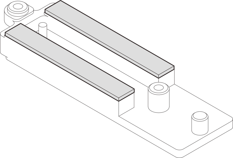
- Paste the VR 2.5 mm Putty Pad to the bottom side of the VR conduction plate. Make sure to follow Gap pad/putty pad replacement guidelines.Figure 2. Putty pads on the bottom side of the VR conduction plate
- Discard the VR conduction plate.
- Install the VR conduction plate to the system board.
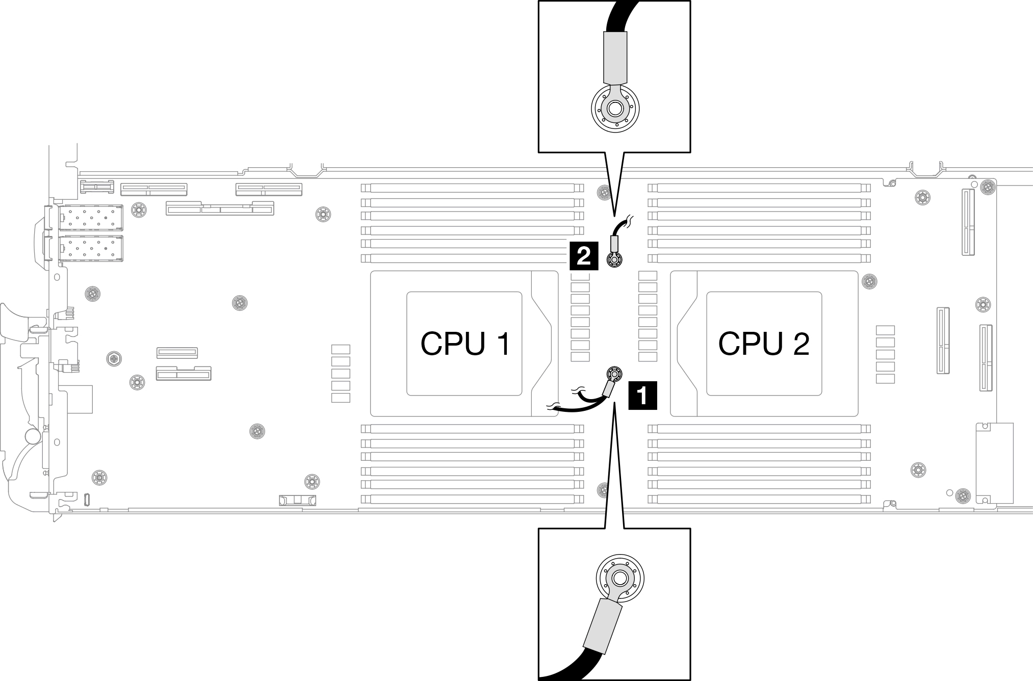
- Locate the screw holes for shielding cable 1/2 and shielding cable 3.
1 Screw hole for shielding cable 1/2 2 Screw hole for shielding cable 3 Figure 3. Location of screw holes of shielding cable 1/2 and 3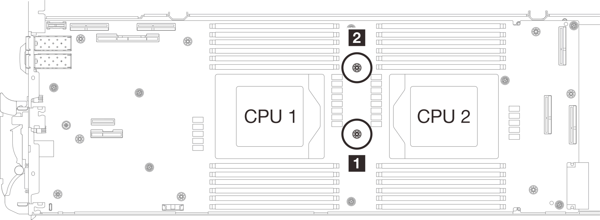
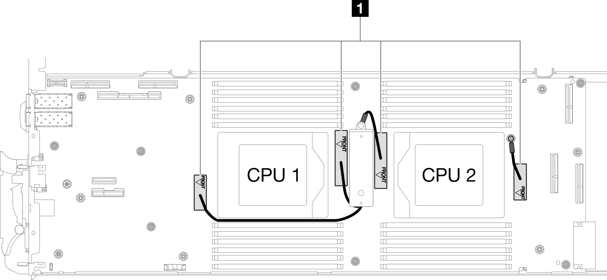
- Align shielding cable 1/2 and shielding cable 3 to the screw holes on system board. Make sure the ring terminals of the cable are placed in the angle shown below.Figure 4. Aligning shielding cable 1/2 and shielding cable 3 with screw holes
 Keep the FRONT marking on the VR conduction plate pointing the front of the tray. Then, place the VR conduction plate on top of the two cable ring terminals.Note
A putty pad is attached to the bottom side of the VR conduction plate. Carefully hold the VR conduction plate to avoid damaging the putty pad.
Figure 5. Aligning VR conduction plate, shielding cables, and system board screw holes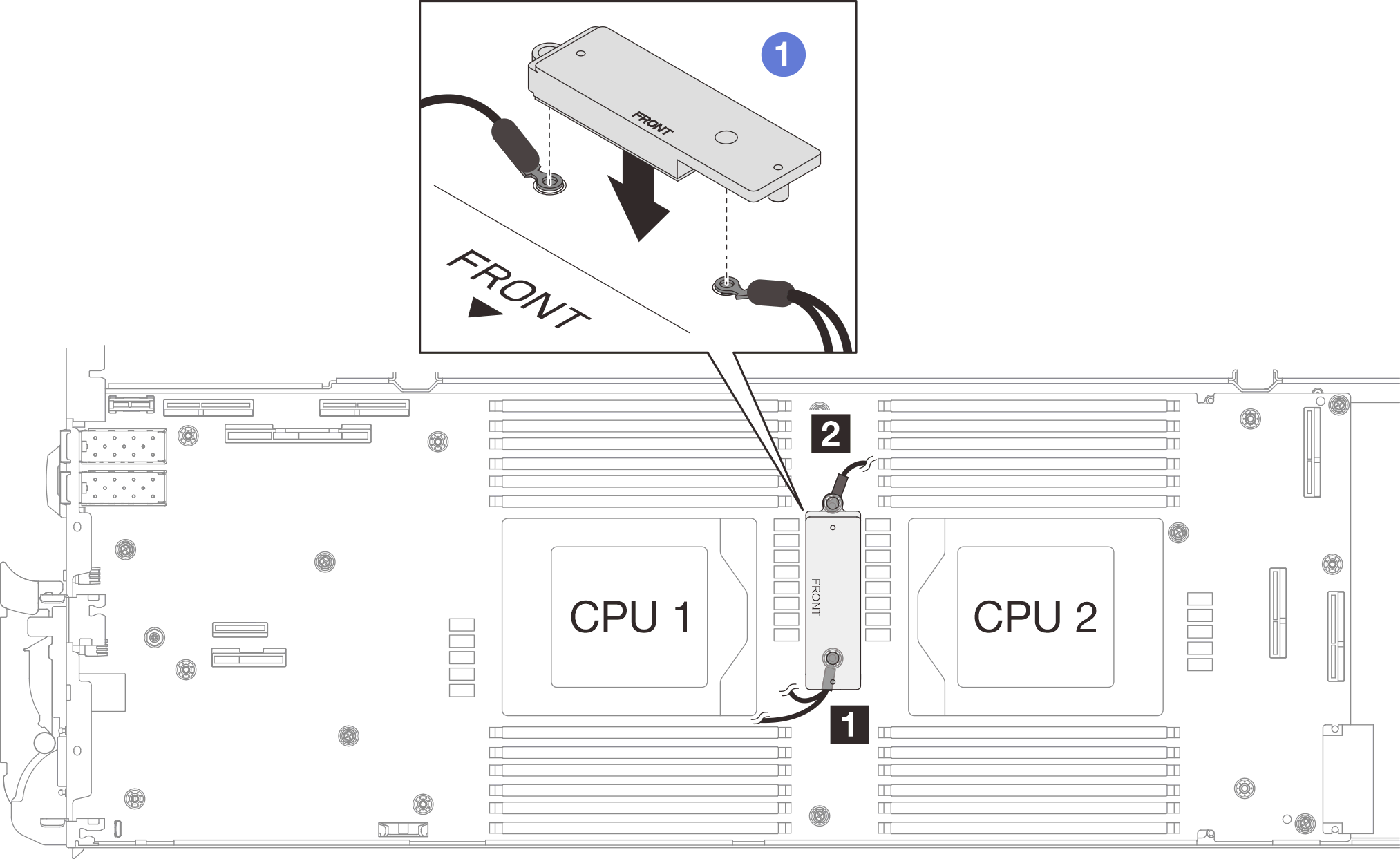
 Slightly press down the VR conduction plate.AttentionThe following items will be secured by screw. Make sure they are aligned and do not block each other.
Screw hole on the system board
The hole on the ring terminal of the shielding cage cable
Screw hole on the VR conduction plate
Figure 6. Pressing on the VR conduction plate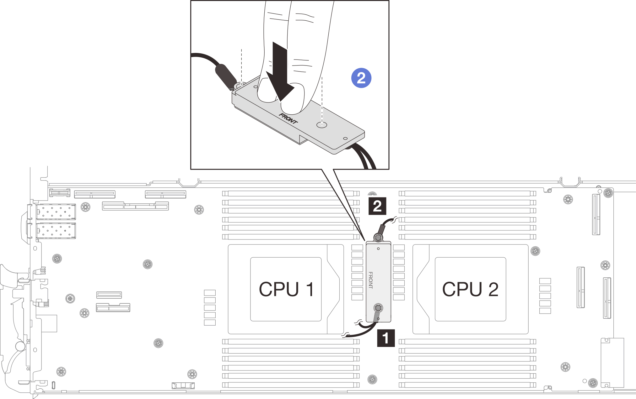
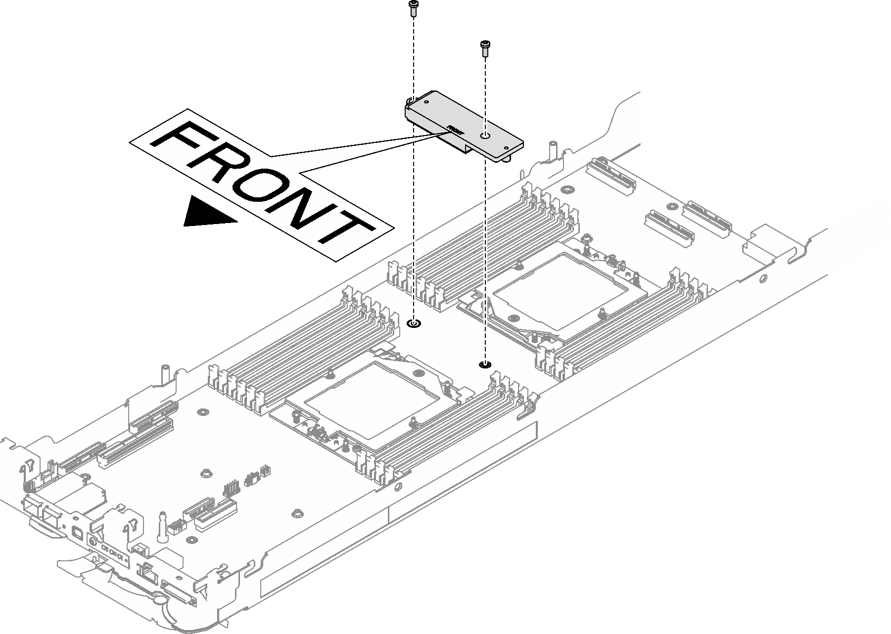
 While pressing down the VR conduction plate, place the screws into the two screw holes on the VR conduction plate. Then, fasten the two screws to secure the cables to the system board. DO NOT fasten the screws until both screws are placed into the VR conduction plate.Figure 7. Installing shielding cable 1/2 and 3
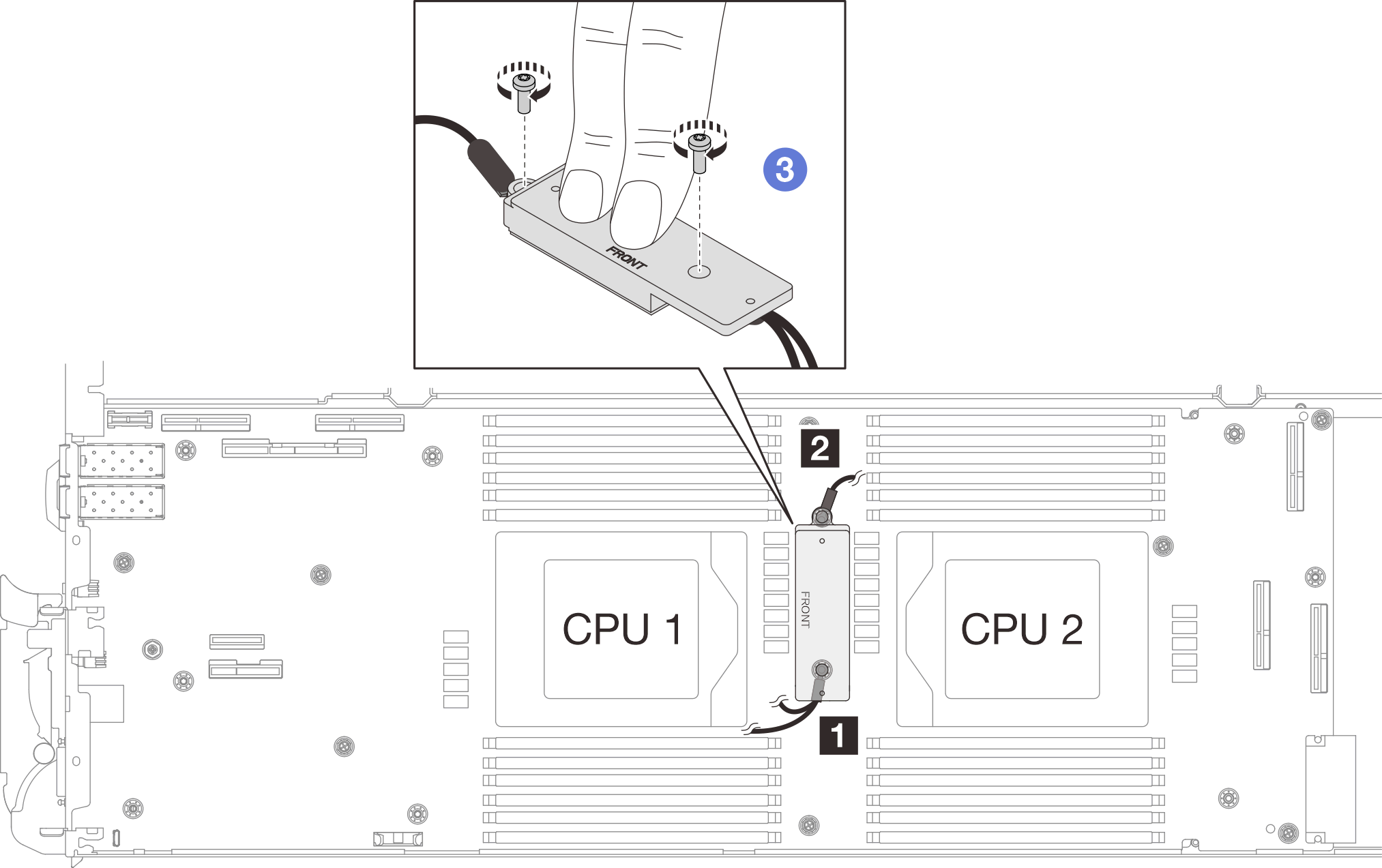
- Locate the screw holes for shielding cable 1/2 and shielding cable 3.
For system board without shielding cables
- Paste VR 1.5mm Putty Pad to the VR conduction plate.
- Discard the VR conduction plate.Figure 8. VR conduction plate removal
- Paste the VR putty pad VR 1.5mm Putty Pad to the bottom side of the VR conduction plate. Make sure to follow Gap pad/putty pad replacement guidelines.Figure 9. Putty pads on the bottom side of the VR conduction plate
- Install the VR conduction plate to the system board.Figure 10. VR conduction plate removal
- Discard the VR conduction plate.
Proceed to install the water loop. See Install the water loop.