Remove the water loop
Use this information to remove the water loop in the SD665 V3 tray.
About this task
Required tools
Make sure you have the required tools listed below in hand to properly replace the component.
SD665 V3 Water Loop Service Kit (The water loop carrier in the Service Kit is reusable, it is recommended to keep it at the facility where the server operates for future replacement needs.)
SD665 V3 Water Loop Putty Pad Kit
(Optional) VR conduction plate
When installing a whole new water loop to the tray, make sure the VR conduction plate on system board is compatible with the water loop model, as specified in the water loop / VR conduction plate support matrix in DWC Product - mandatory Maintenance KIT and Thermal Pads. If replacing VR conduction plate is needed, see Install the VR conduction plate for water loop replacement.
Drive gap pad or putty pad kits according to the drives installed in the tray. See their respective replacement procedures for more information.
ConnectX series adapter putty pad kits according to the ConnectX adapter installed in the tray. See their respective replacement procedures for more information.
Screws and screwdrivers
Prepare the following screwdrivers to ensure you can install and remove corresponding screws properly.Screwdriver Type Screw Type Torx T10 head screwdriver Torx T10 screw Torx T20 head screwdriver Torx T20 screw Phillips #2 head screwdriver Phillips #2 screw
Read Installation Guidelines and Safety inspection checklist to ensure that you work safely.
Turn off the corresponding DWC tray that you are going to perform the task on.
Disconnect all external cables from the enclosure.
Use extra force to disconnect QSFP cables if they are connected to the solution.
To avoid damaging the water loop, always use the water loop carrier when removing, installing or folding the water loop.
Procedure
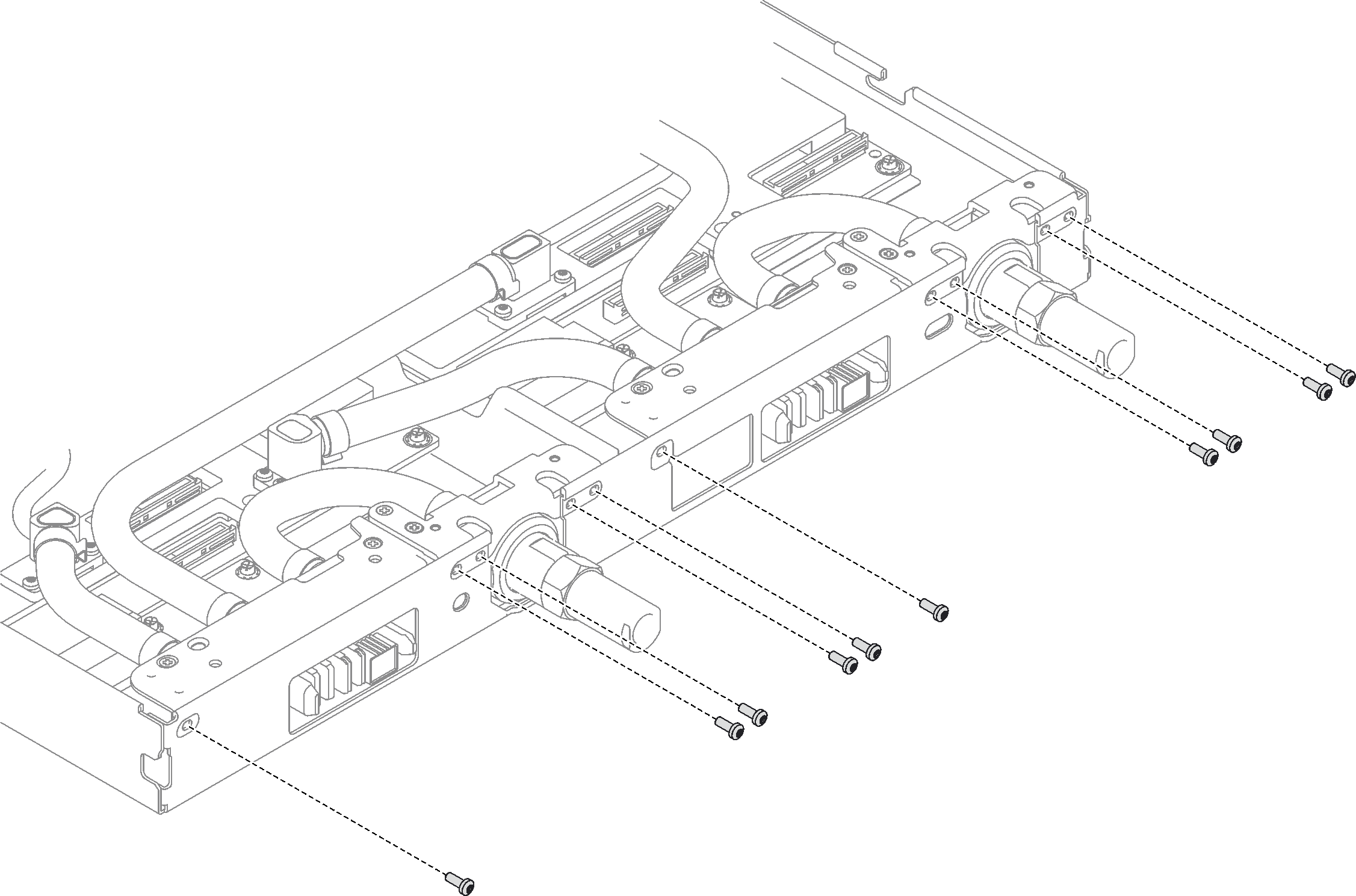
- Remove the ten screws to loosen the quick connect.Figure 1. Quick connect screw removal
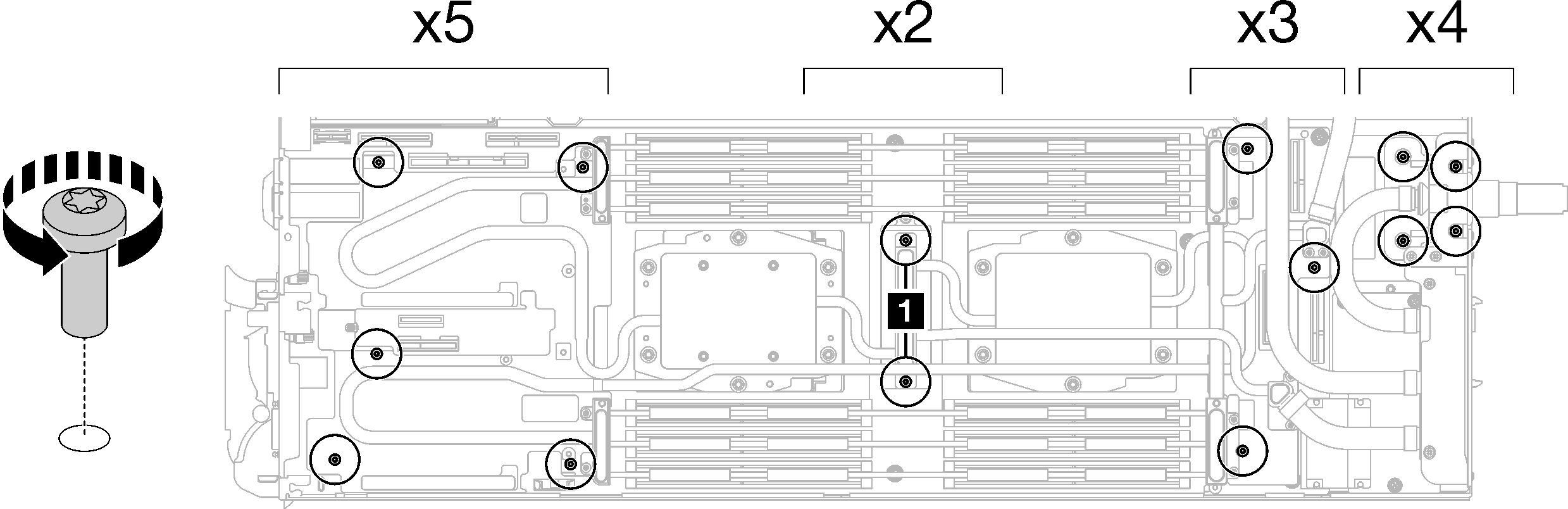
- Remove water loop screws and quick connect screws (14x Torx T10 screws per node) with a torque screwdriver set to the proper torque.Note
For reference, the torque required for the screws to be fully tightened/removed is 5.0+/- 0.5 lbf-in, 0.55+/- 0.05 N-M.
When removing the 1 VR cold plate screws (x2), remove the washers, too. Make sure to keep the washers for future use. (Depending on the configurations, there may not be any washers on the VR cold plate. In this case, there is no need to remove and keep the washers.)
Figure 2. VR cold plate screws with washers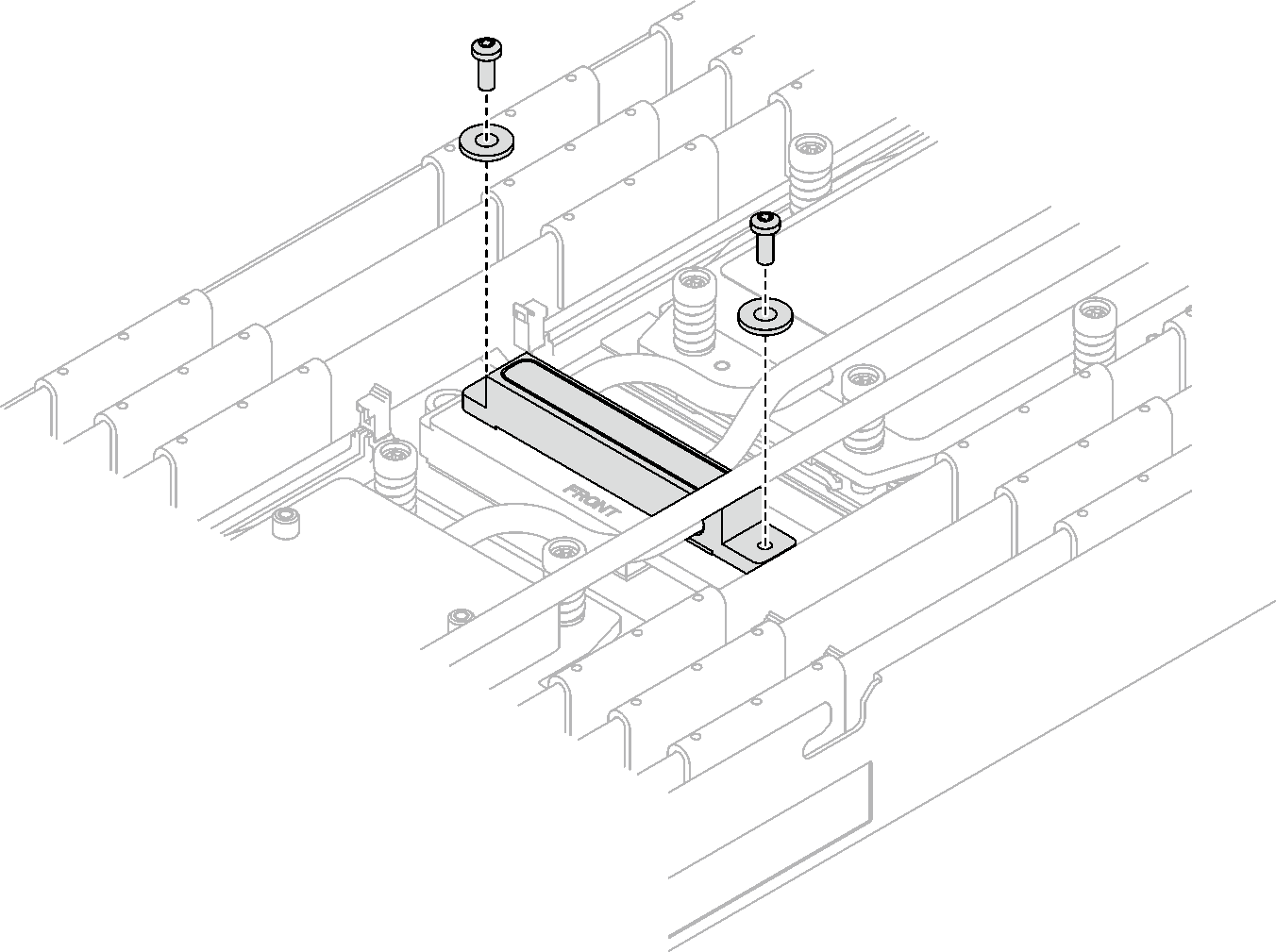
Figure 3. Water loop screw removal1 VR cold plate screws (x2)
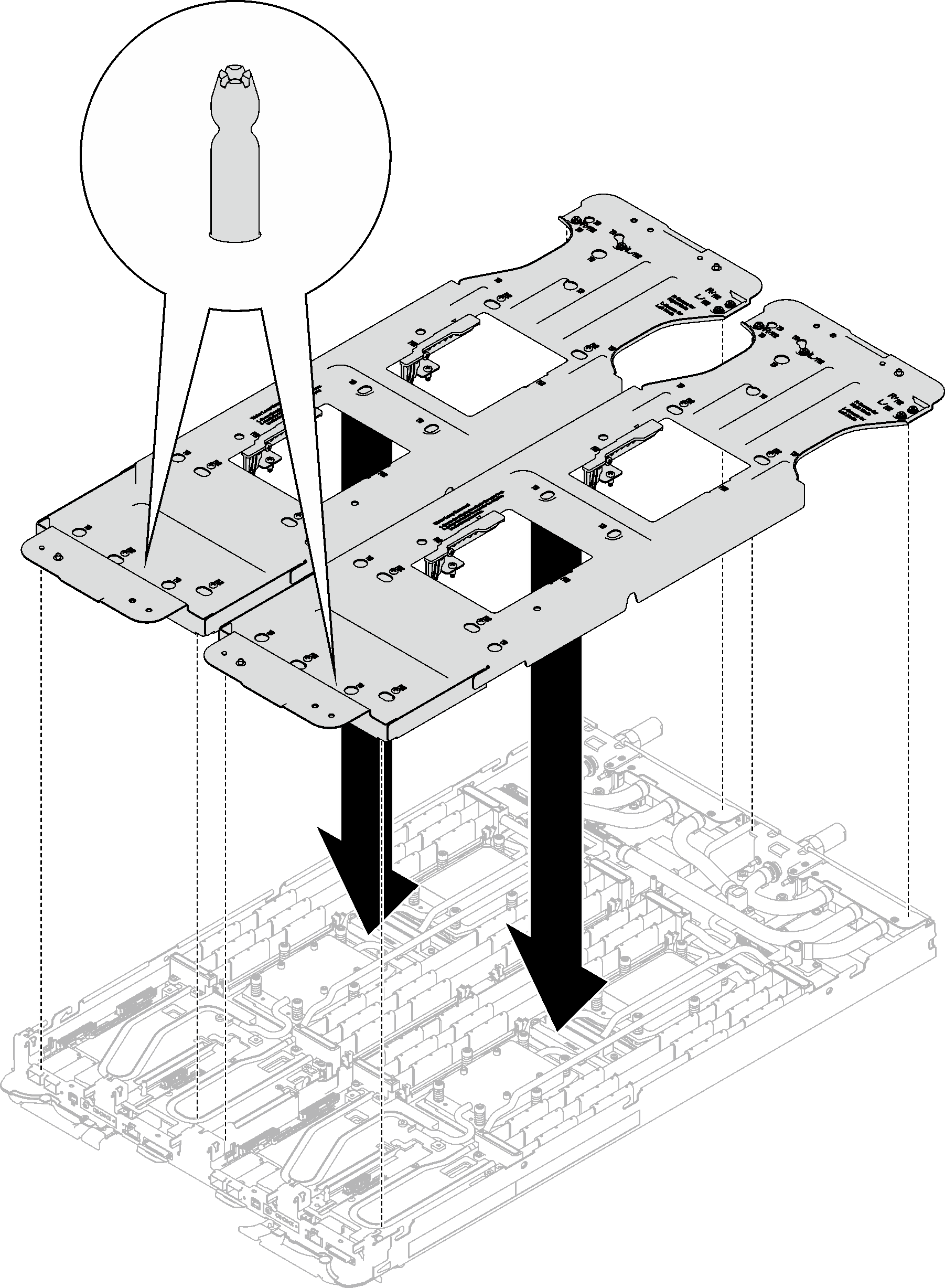
- Orient two water loop carriers with the guide pins; then, gently put the two water loop carriers down and ensure they are seated firmly on the water loop.Figure 4. Water loop carrier installation
- Tighten water loop carrier screws (24x Phillips #2 screws for two nodes).NoteThe screw holes on the rear of the carrier are marked with
L and R. Select screw holes marked as L when the carrier is on the left node, and R for the right node. Figure 5. Water loop carrier screws installation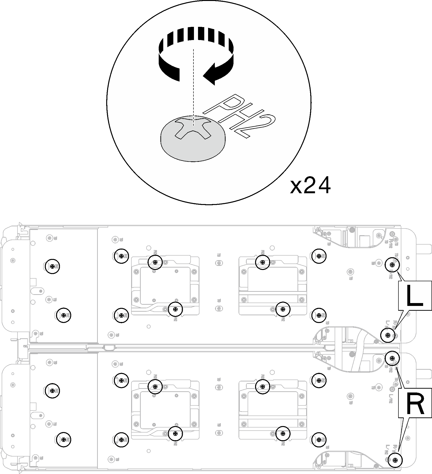
- Remove processor cold plate screws (12x Torx T20 screws per node). Follow the screw sequence specified on the processor cold plate label and loosen the screws with a general screwdriver torque screwdriver. Fully loosen each screw; then, proceed to the next screw.NoteFor reference, the torque required for the screws to be fully tightened/removed is 1.12-1.46 newton-meters, 10-13 inch-poundsFigure 6. Processor cold plate label
Fully loosen each screw in this order:
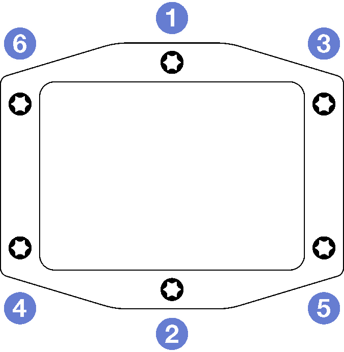 Figure 7. Processor cold plate removal
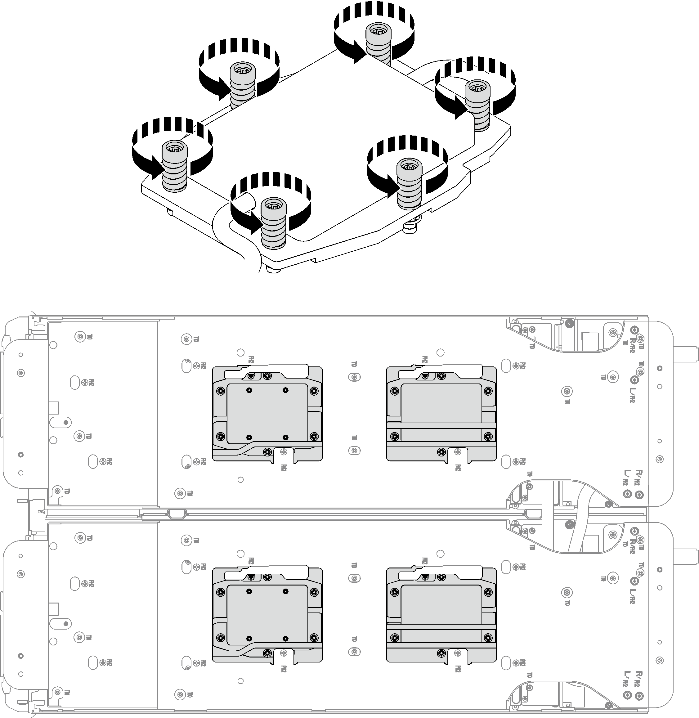
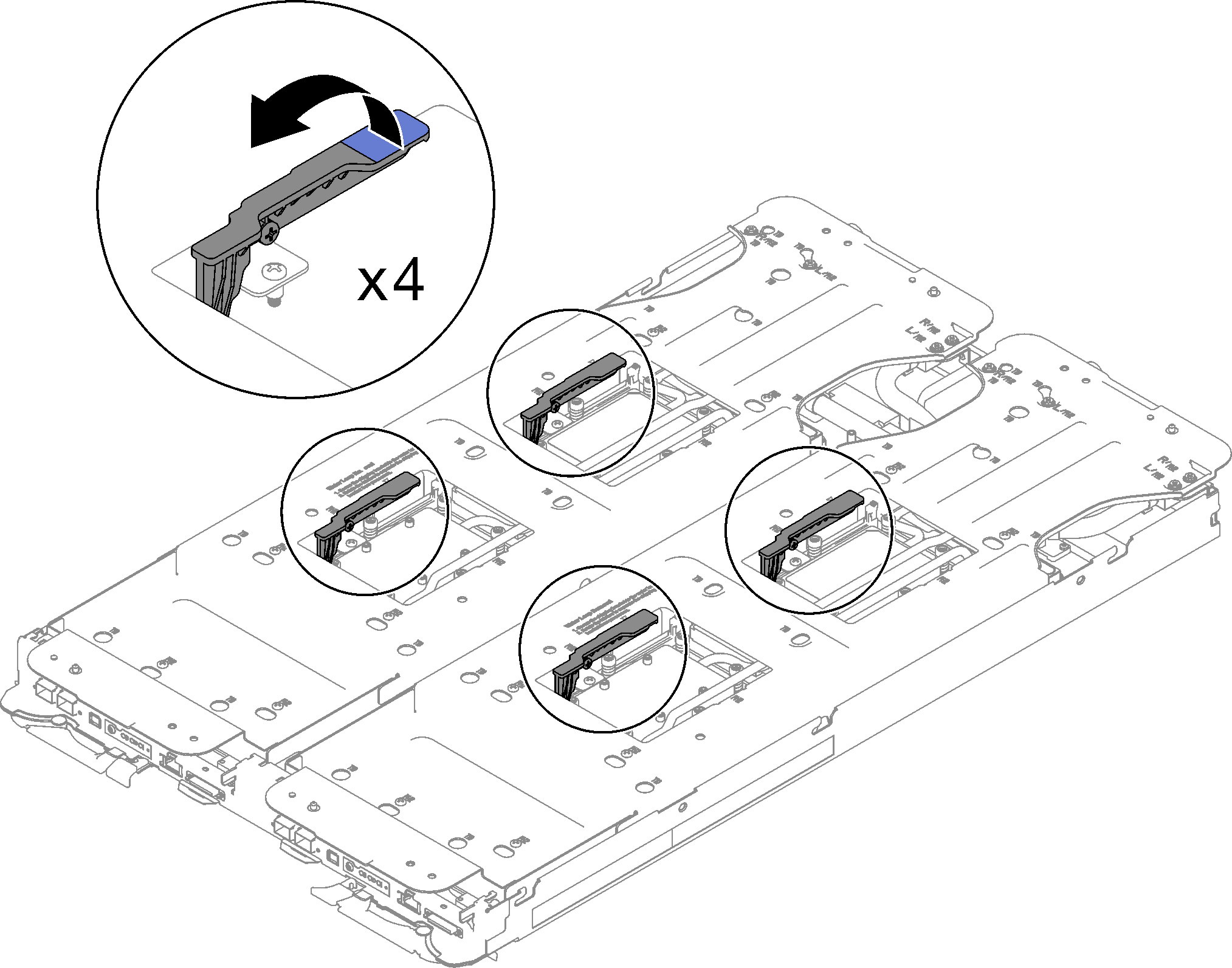
- Rotate the latches on the water loop carrier to separate the processor cold plates from processors.Figure 8. Separate water loop from processor
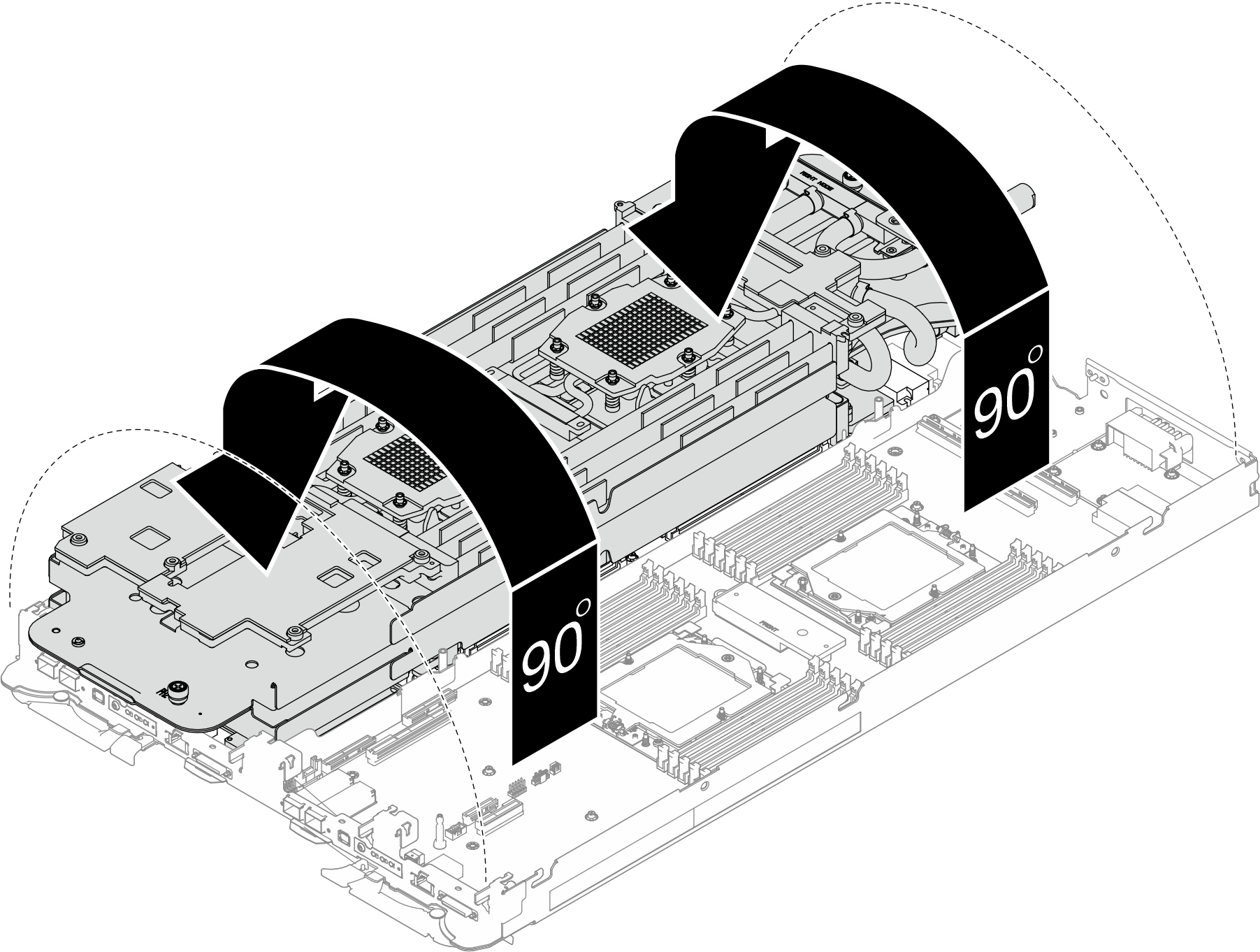
- Do not tilt the water loop. Keep the water loop horizontal with the tray. Slightly lift up the water loop, and carefully rotate the water loop so one half is sitting on top of the other half.Figure 9. Folding the water loop
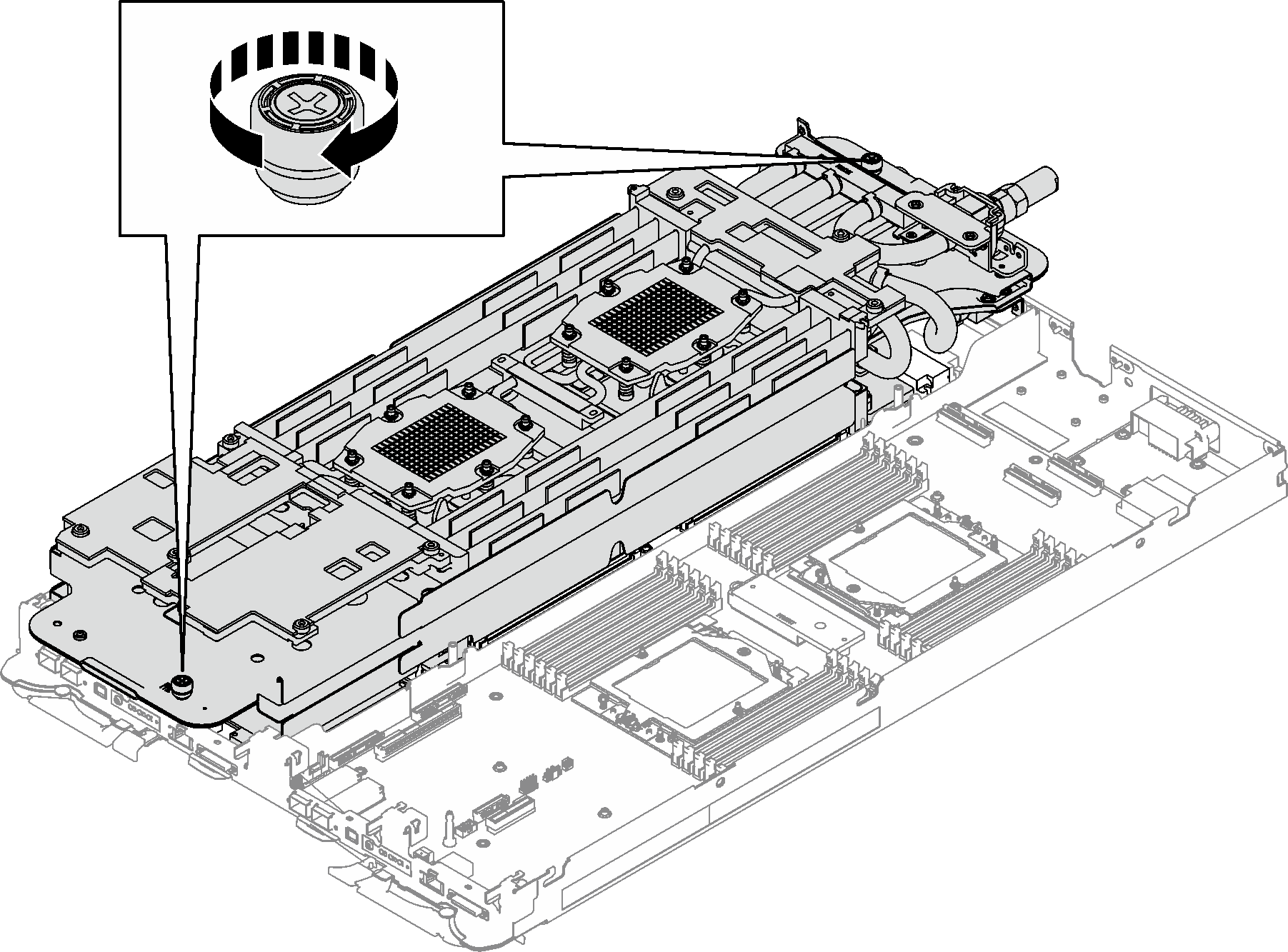
- Fasten two captive thumbscrews to secure water loop carriers to each other.Figure 10. Tightening captive thumbscrews
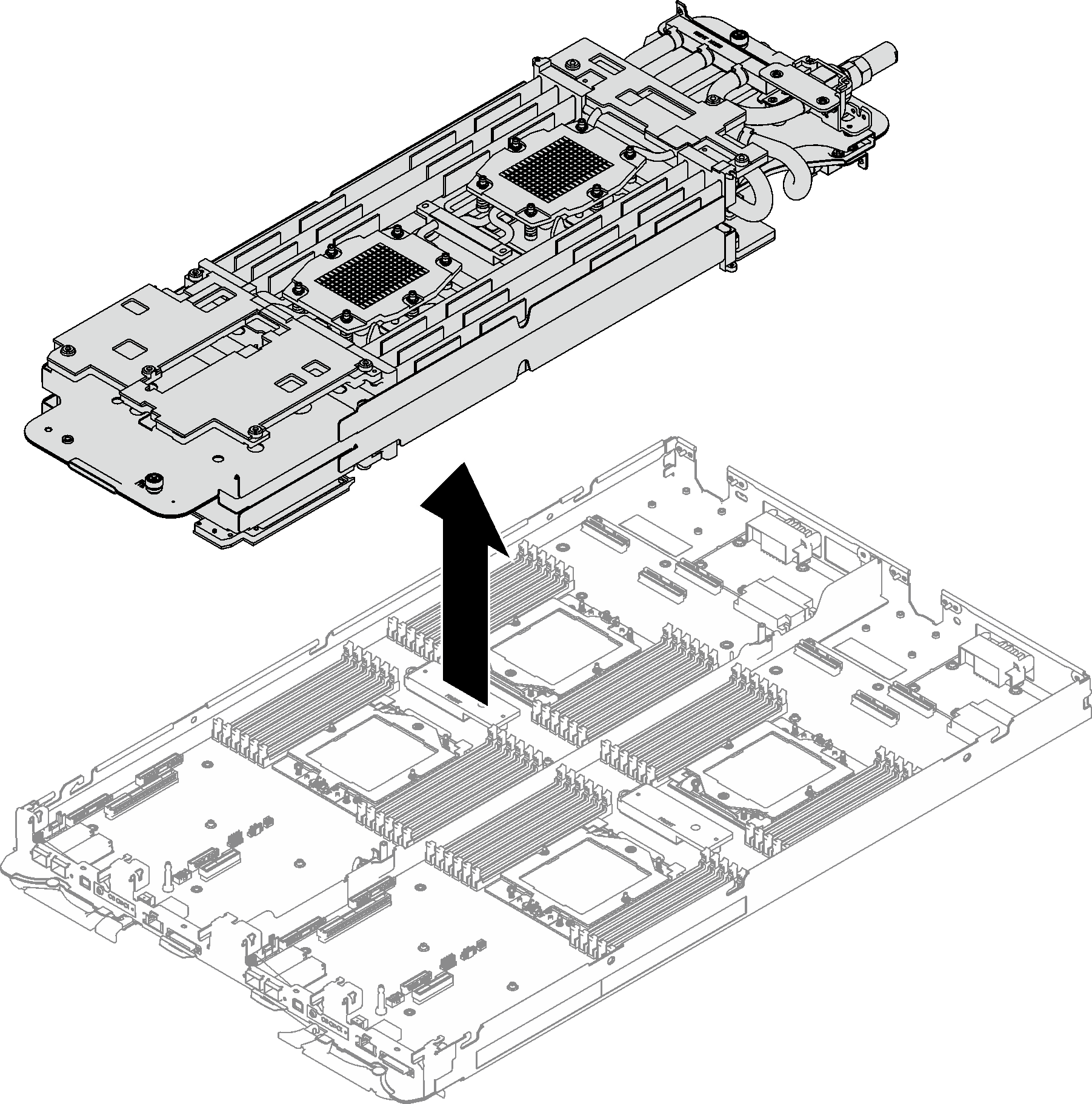
- Carefully lift the water loop up off the system board and out of the node.Figure 11. Water loop removal
If you are instructed to return the component or optional device, follow all packaging instructions, and use any packaging materials for shipping that are supplied to you.
Demo video