Remove a PCIe riser assembly (ConnectX-7 NDR 400)
Use this information to remove a PCIe riser assembly with ConnectX-7 NDR 400 adapter.
About this task
Required tools
Make sure you have the ConnectX-7 NDR400 Putty Pad Kit to properly replace the component. Putty pad cannot be reused. Whenever a component is removed, putty pads must be replaced with new ones before reinstalling the component.
Read Installation Guidelines and Safety inspection checklist to ensure that you work safely.
Turn off the corresponding DWC tray that you are going to perform the task on.
Disconnect all external cables from the enclosure.
Use extra force to disconnect QSFP cables if they are connected to the solution.
Procedure
- If applicable, remove the interconnect cable from the node.
 Remove the two screws from the interconnect cable.
 Remove the interconnect cable from the water loop.
 Remove the two washers from the water loop.
Figure 1. Interconnect cable removal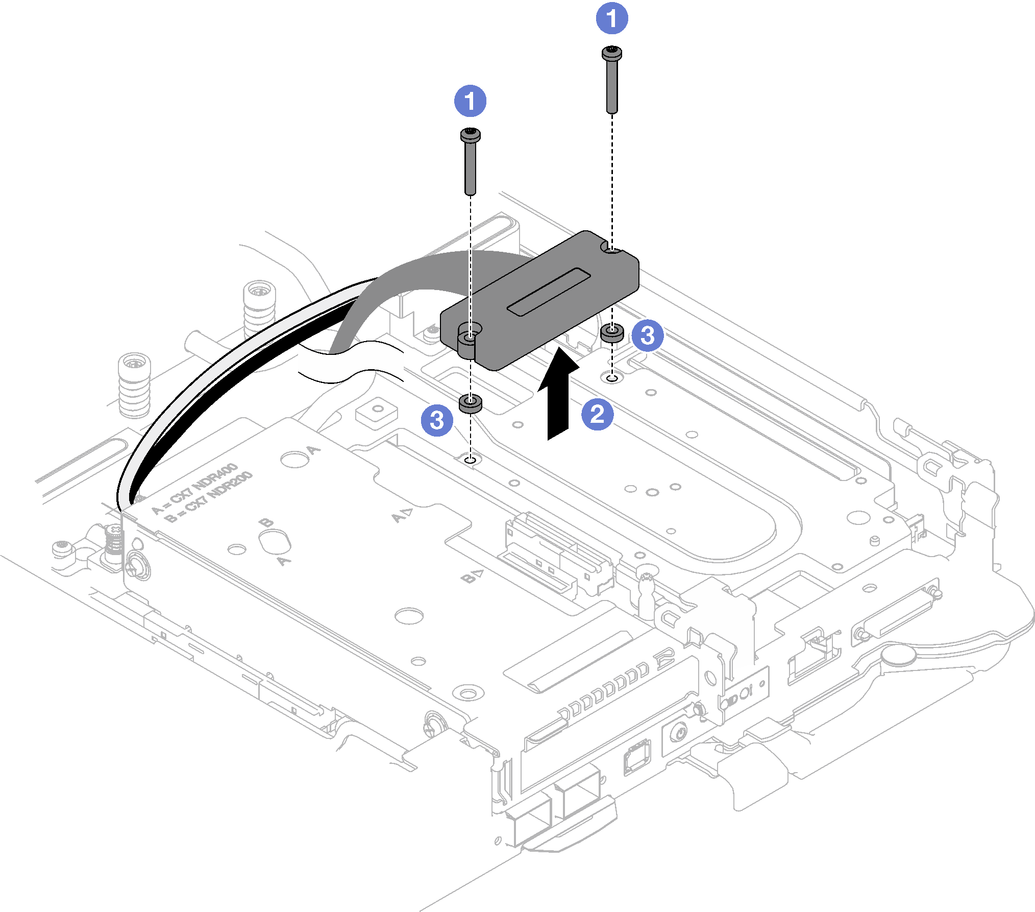
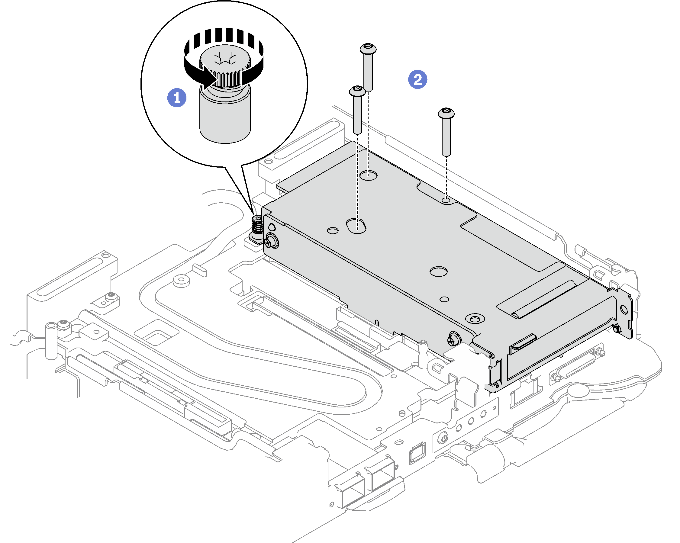
- Remove the PCIe riser assembly.
- Loosen the captive screw on the PCIe riser assembly.
- Remove the three screws that secure the riser assembly.NoteThe following illustration might differ slightly from your hardware, but the removal method is the same.Figure 2. PCIe riser assembly removal
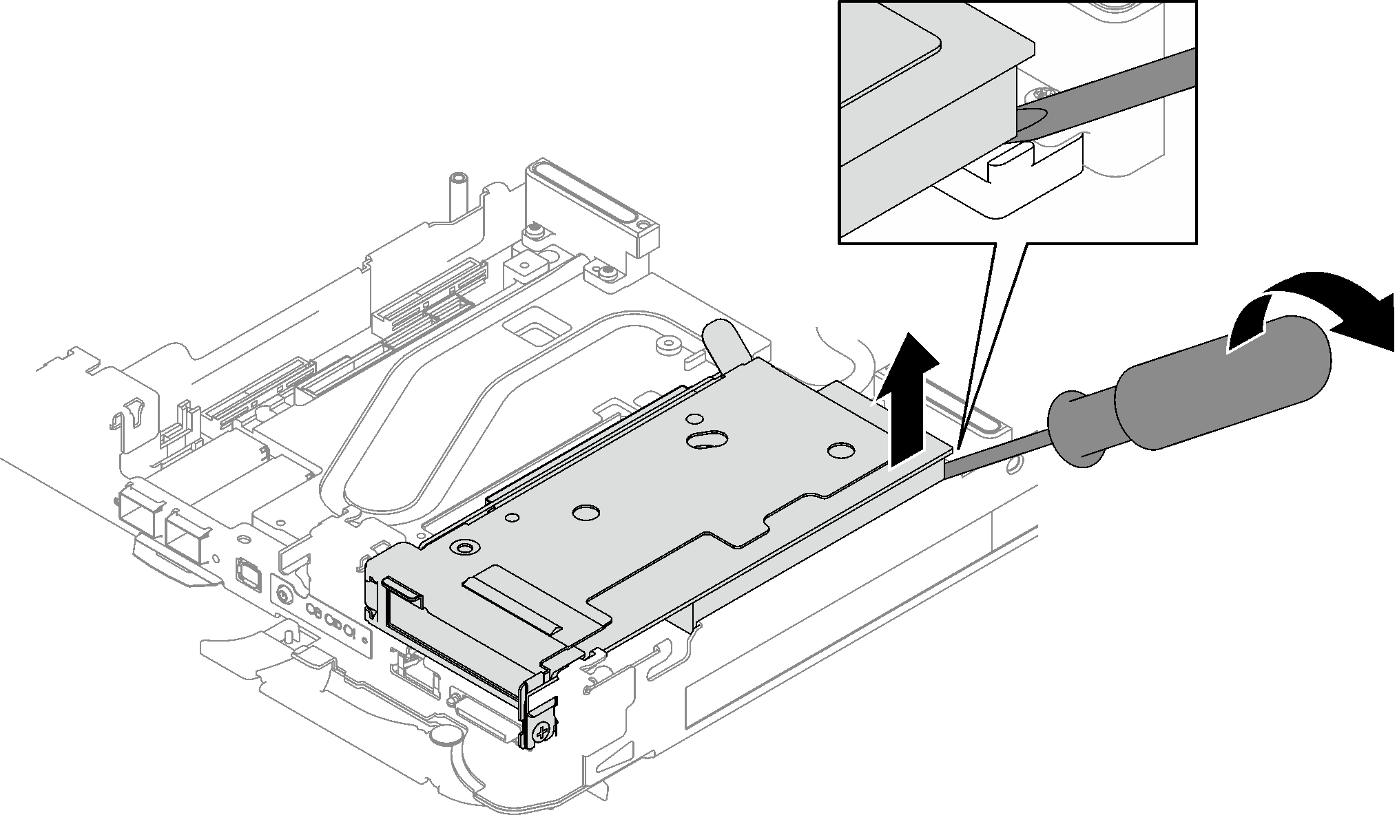
- Insert a flat head screwdriver into the gap between the PCIe adapter and the interface plate; then, slightly rotate the flat head screwdriver to release the PCIe riser cage from the water loop cold plate.Figure 3. Releasing the PCIe riser cage from the water loop cold plate
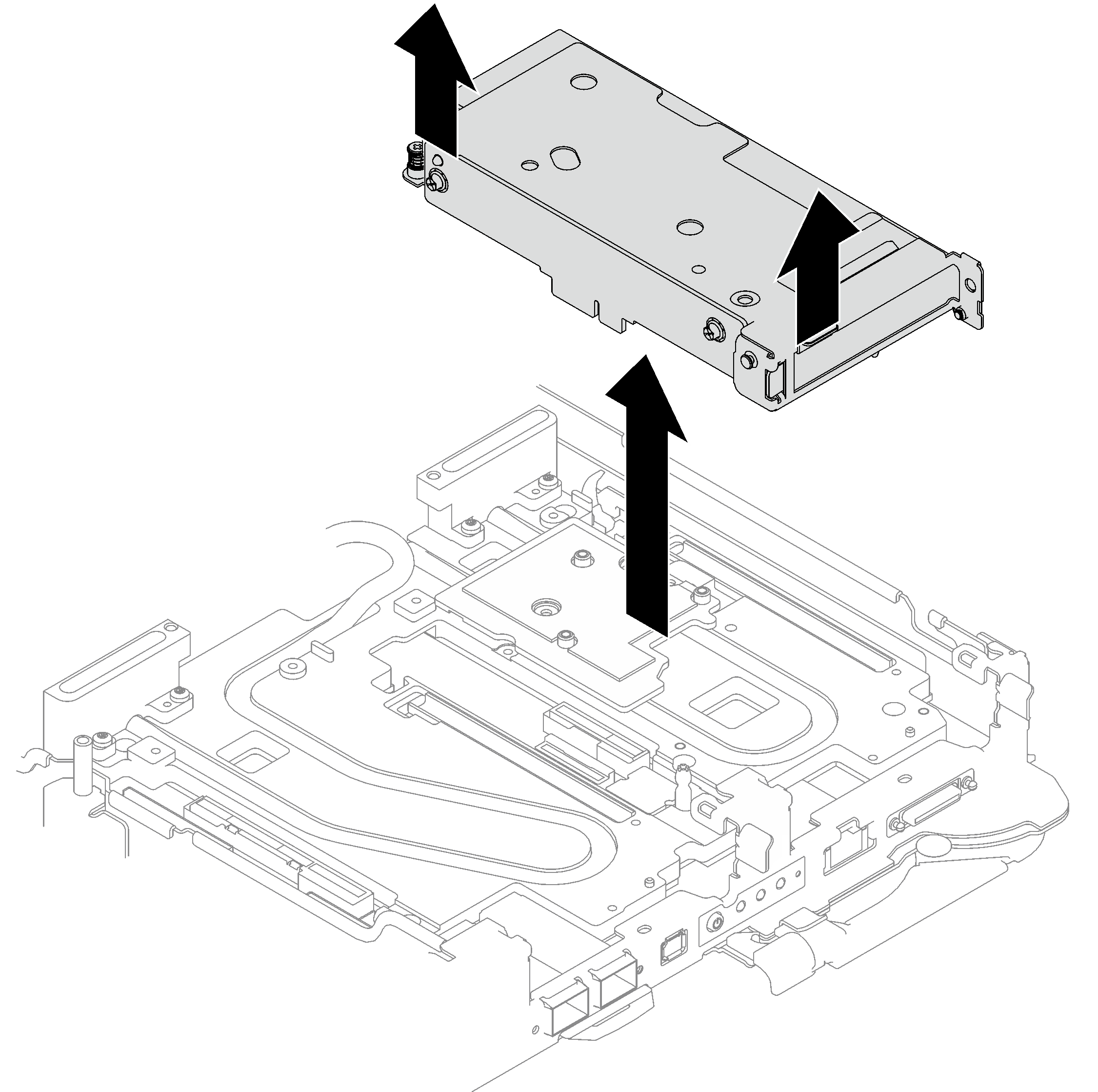
- Carefully grasp the PCIe riser-cage assembly by its edges and remove it out of the node.Figure 4. Removing the PCIe riser cage assembly
- If necessary, remove the interface plate.
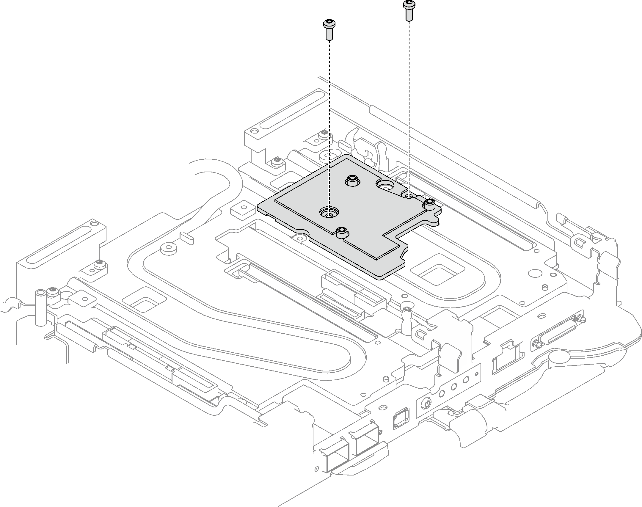
- Remove the two Phillips #2 screws that secure the interface plate.Figure 5. Interface plate removal
- Release the interface plate with a flat head screwdriver. (If a flat head screwdriver is not available, the DIMM tool can also be used.)
There are two openings (marked with black triangle in the illustration below) on the bottom side of the interface plate for inserting a flat head screwdriver—select the one that is accessible for the flat head screwdriver.
Insert a flat head screwdriver into the opening; then, slightly rotate the screwdriver to release the interface plate from the water loop cold plate.
Figure 6. Locations of openings on the bottom side of the interface plate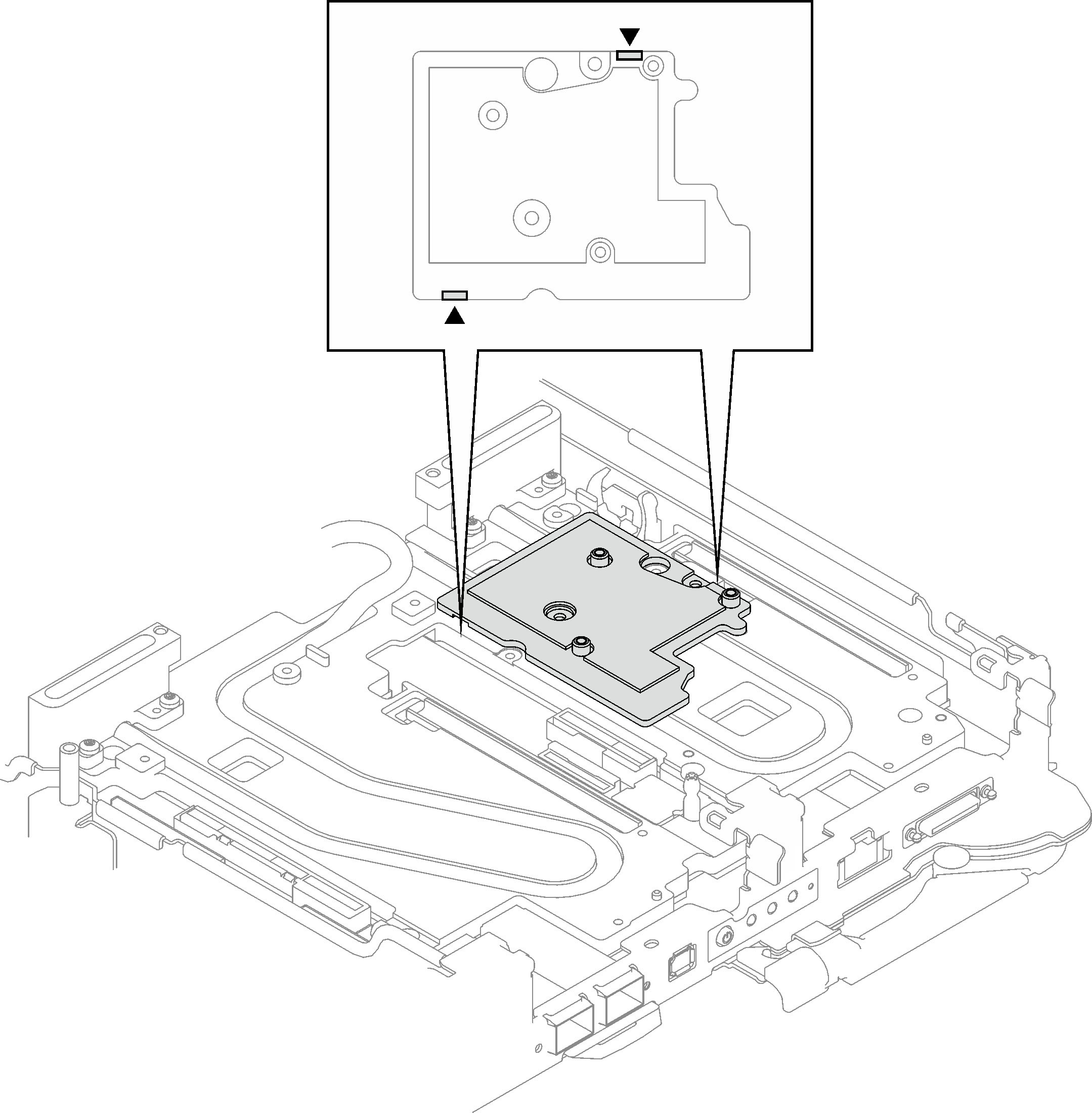 Figure 7. Releasing the interface plate from water loop cold plate
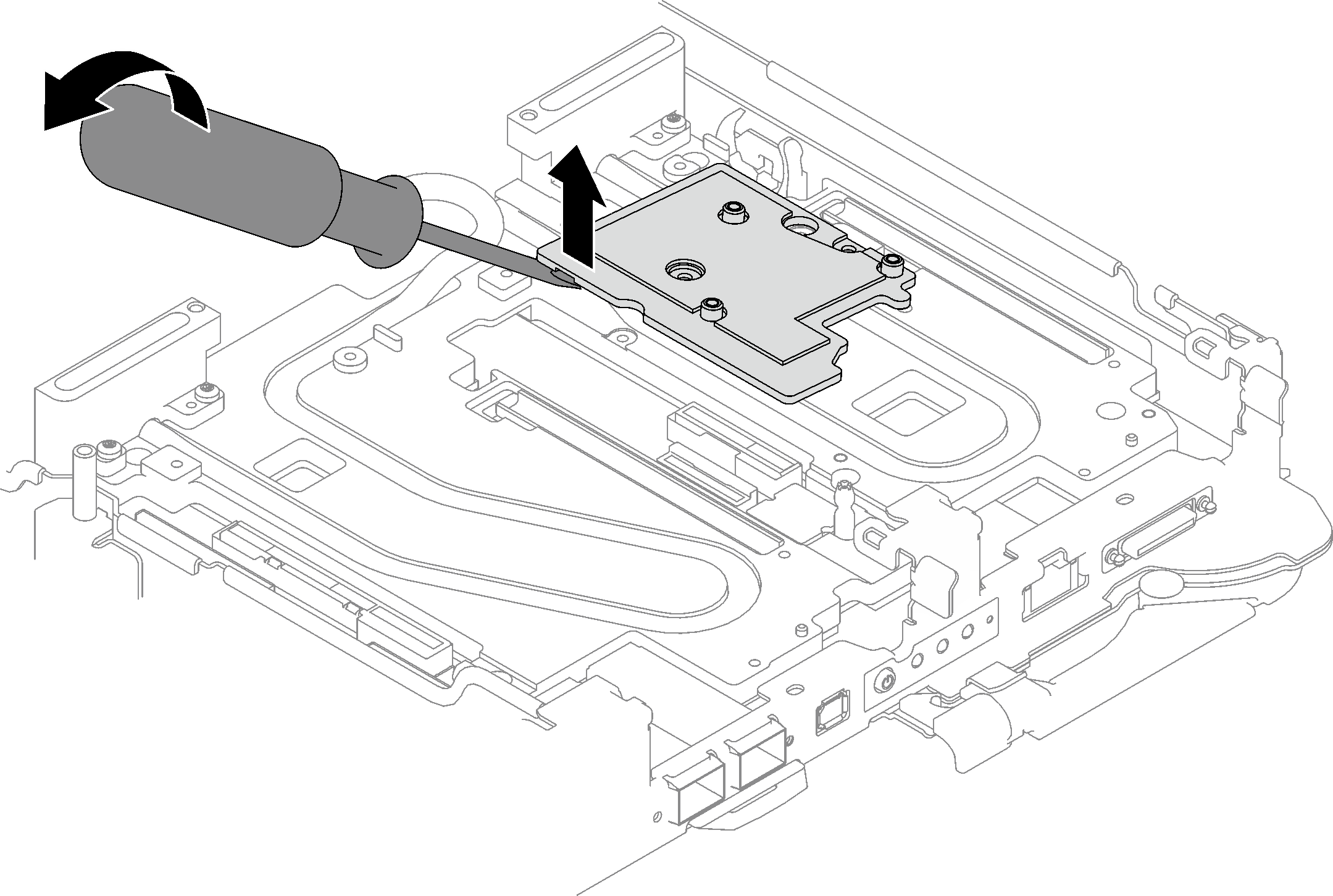
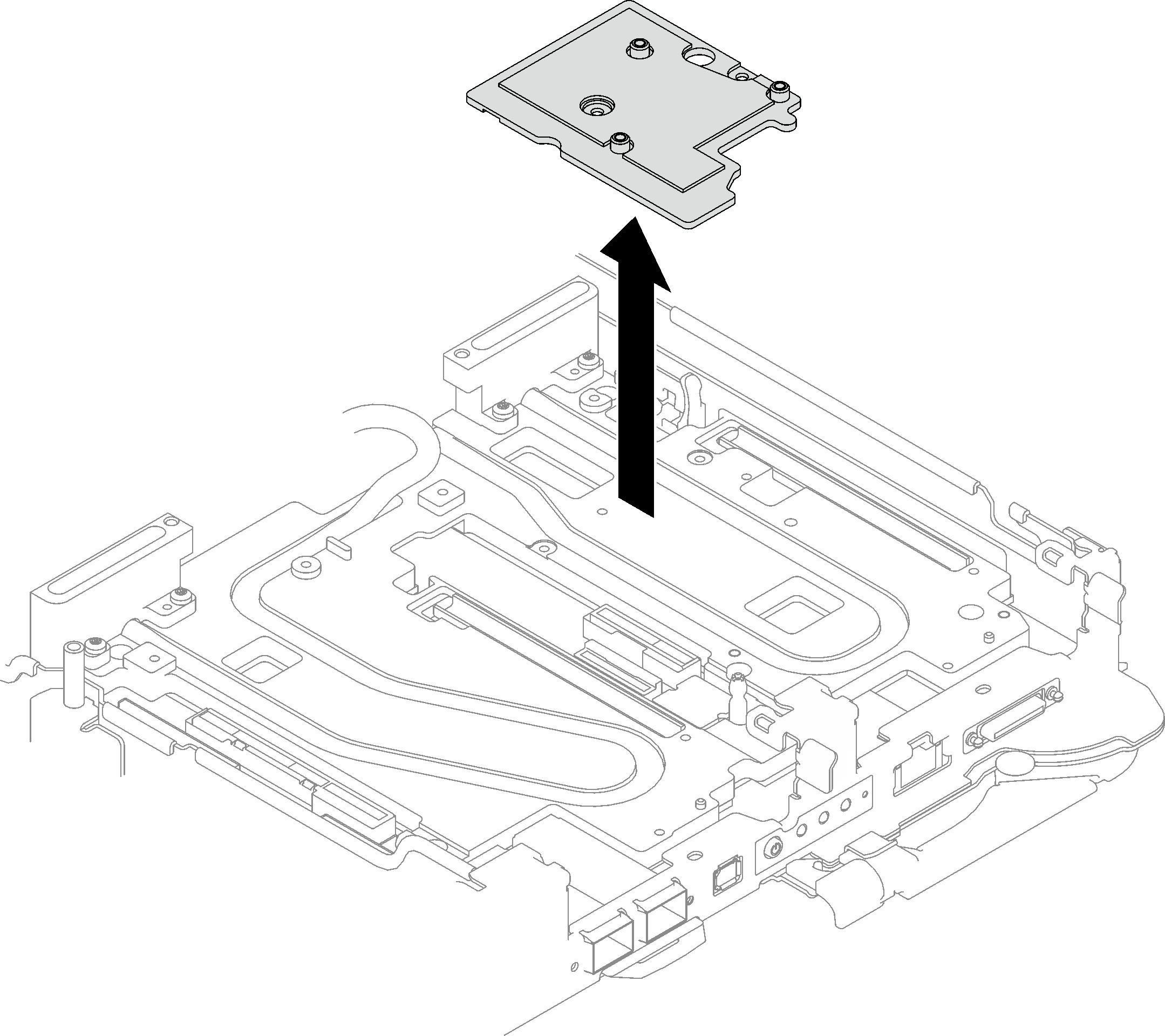
- Remove the interface plate from the tray.Figure 8. Removing the interface plate
- Remove the two Phillips #2 screws that secure the interface plate.
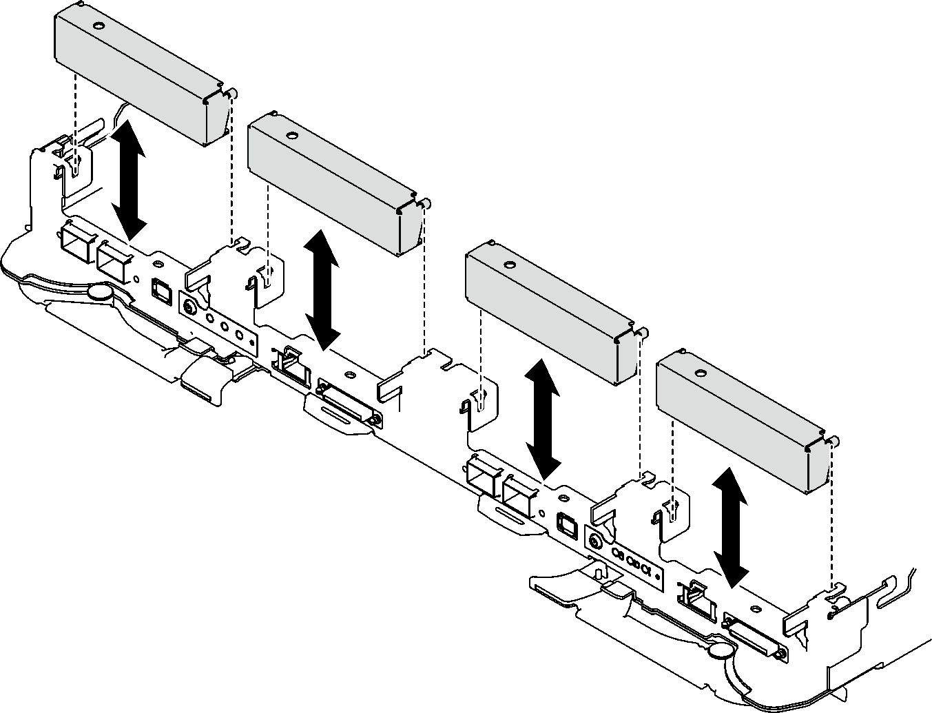
- If necessary, install the blank bezel fillers.Figure 9. Blank bezel filler installation
If you are instructed to return the component or optional device, follow all packaging instructions, and use any packaging materials for shipping that are supplied to you.
If necessary, remove Mylar film from the PCIe riser assembly.
Remove the two screws with a 3/16" hex head screwdriver; then, separate the expansion board from the cage.
Figure 10. Expansion board removal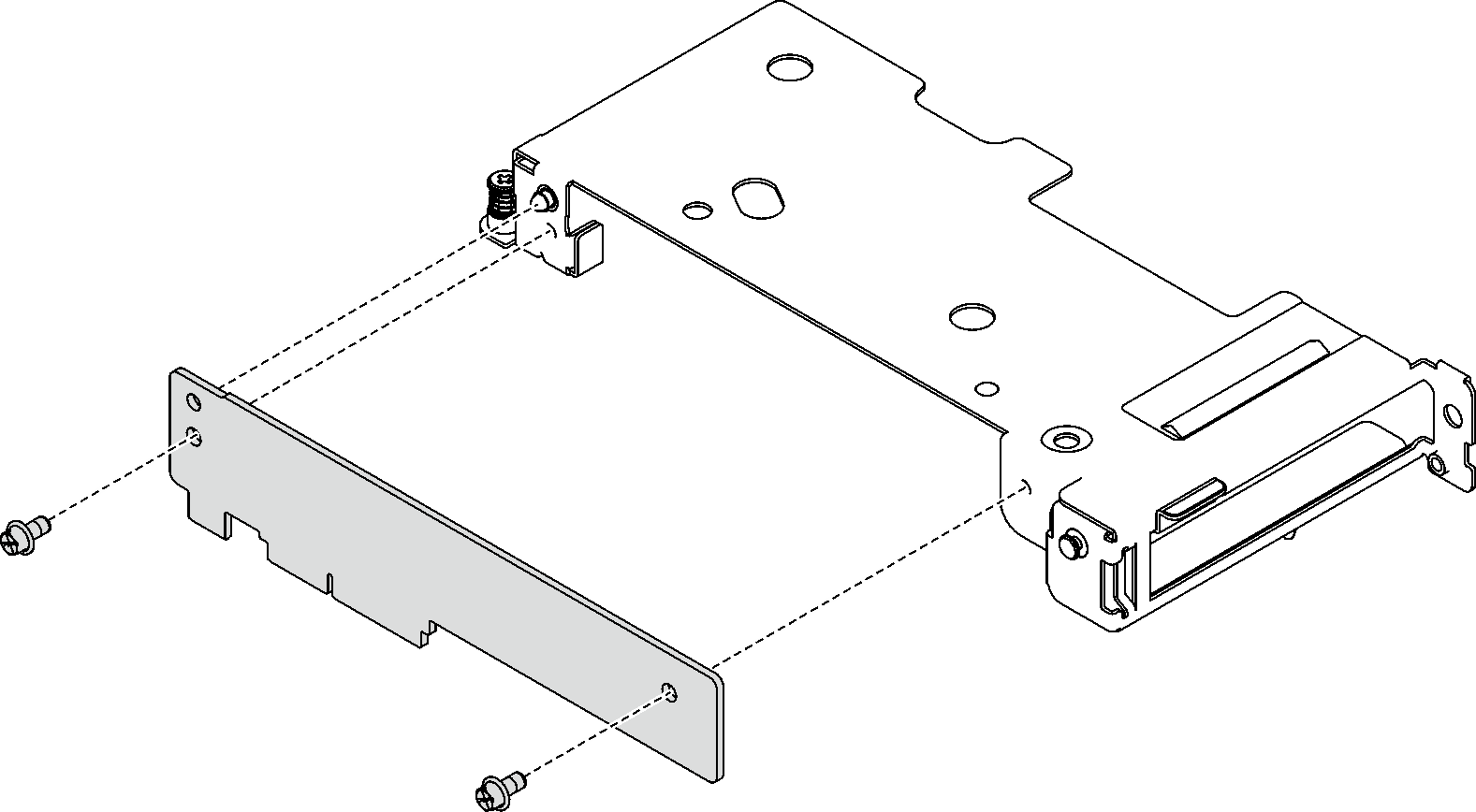
Recycle the unit in compliance with local regulations.
Demo video