Remove a drive cage assembly
Use this information to remove a drive cage assembly.
About this task
Required tools
You may need the SD665 V3 Water Loop Gap Pad Kit to properly replace the component.
Attention
Read Installation Guidelines and Safety inspection checklist to ensure that you work safely.
Turn off the corresponding DWC tray that you are going to perform the task on.
Disconnect all external cables from the enclosure.
Use extra force to disconnect QSFP cables if they are connected to the solution.
Procedure
- Disconnect the cables from the system board.Figure 1. Drive assembly cable routing for SATA drives
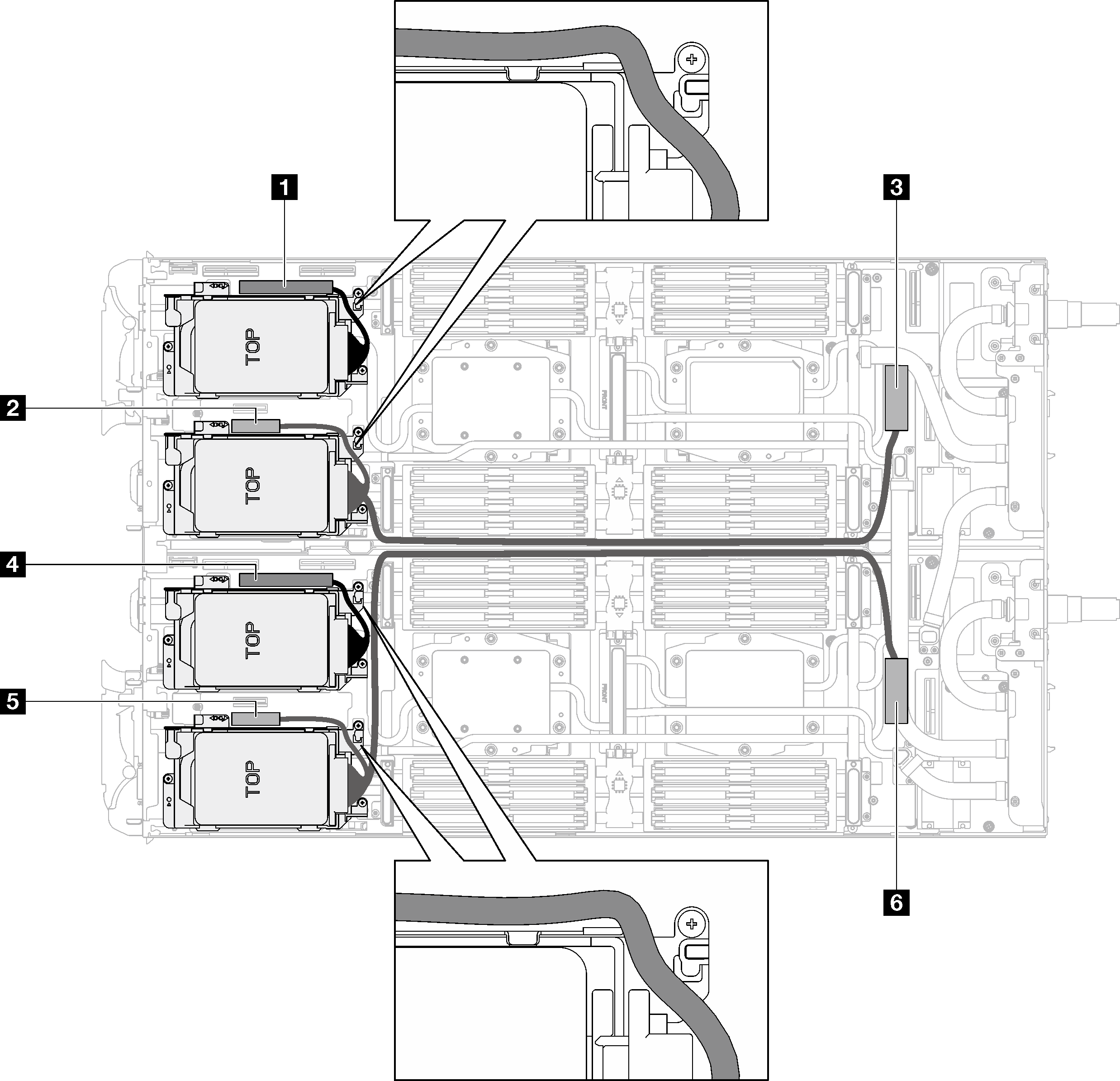
Table 1. Drive assembly cable routing for SATA drives System board connector Node 1 PCIe 2/SATA– drive 2/3 Left node 2 Power and sideband signal for drive bay 0/1 3 PCIe 1/SATA – drive 0/1 4 PCIe 2/SATA– drive 2/3 Right node 5 Power and sideband signal for drive bay 0/1 6 PCIe 1/SATA – drive 0/1 Figure 2. Drive assembly cable routing for all NVMe drives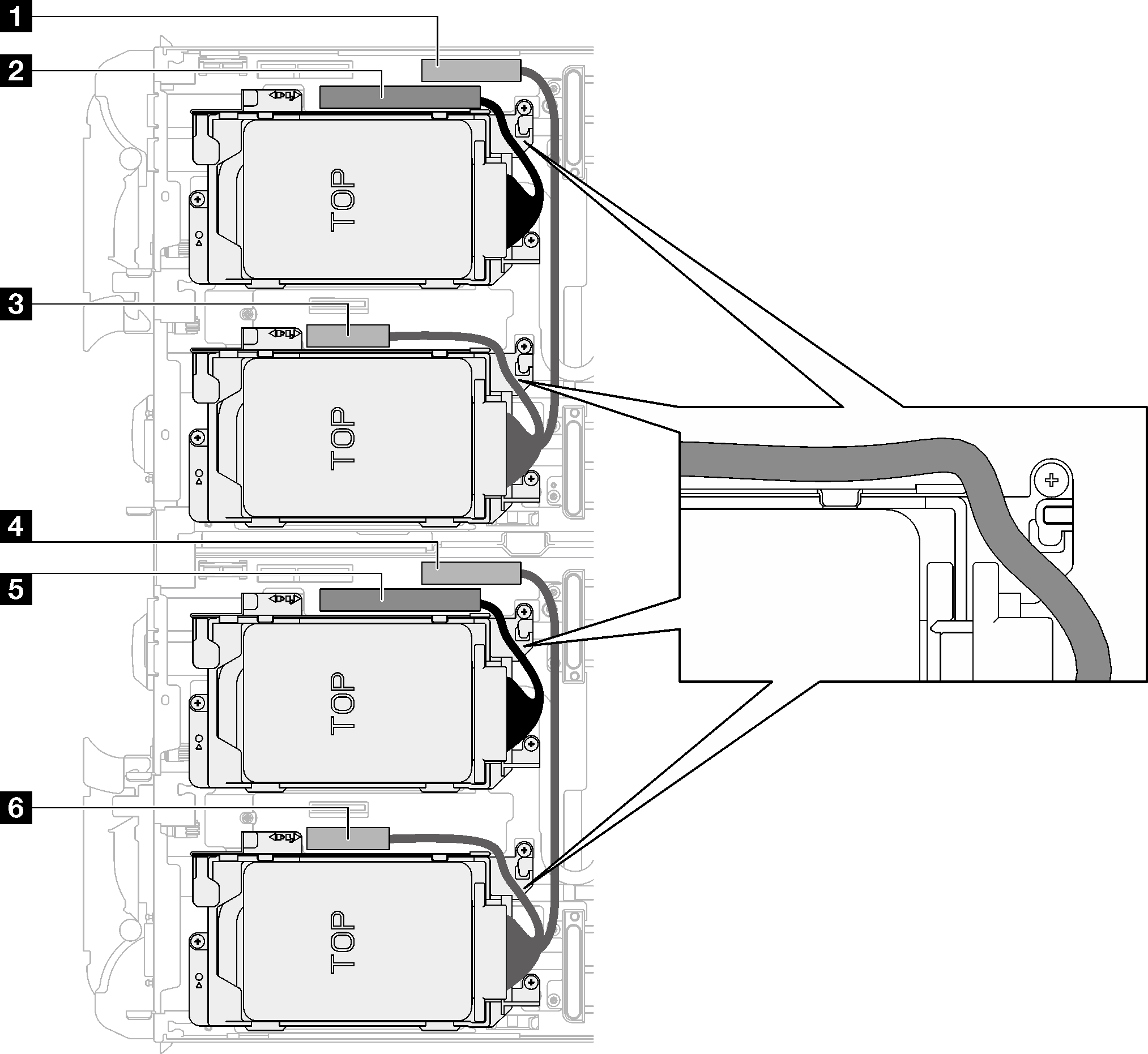
Table 2. Drive assembly cable routing for all NVMe drives System board connector Node 1 PCIe 3 – drive bay 0/1 (NVMe only) Left node 2 PCIe 2/SATA– drive 2/3 3 Power and sideband signal for riser 1 or drive bay 0/1 4 PCIe 3 – drive bay 0/1 (NVMe only) Right node 5 PCIe 2/SATA– drive 2/3 6 Power and sideband signal for riser 1 or drive bay 0/1 - Remove the drive cage assembly.
 Remove the 3 screws.
 Remove the drive assembly out of the node.
NoteThe following illustration might differ slightly from your hardware, but the installation method is the same.Figure 3. One 7 mm drive cage assembly removal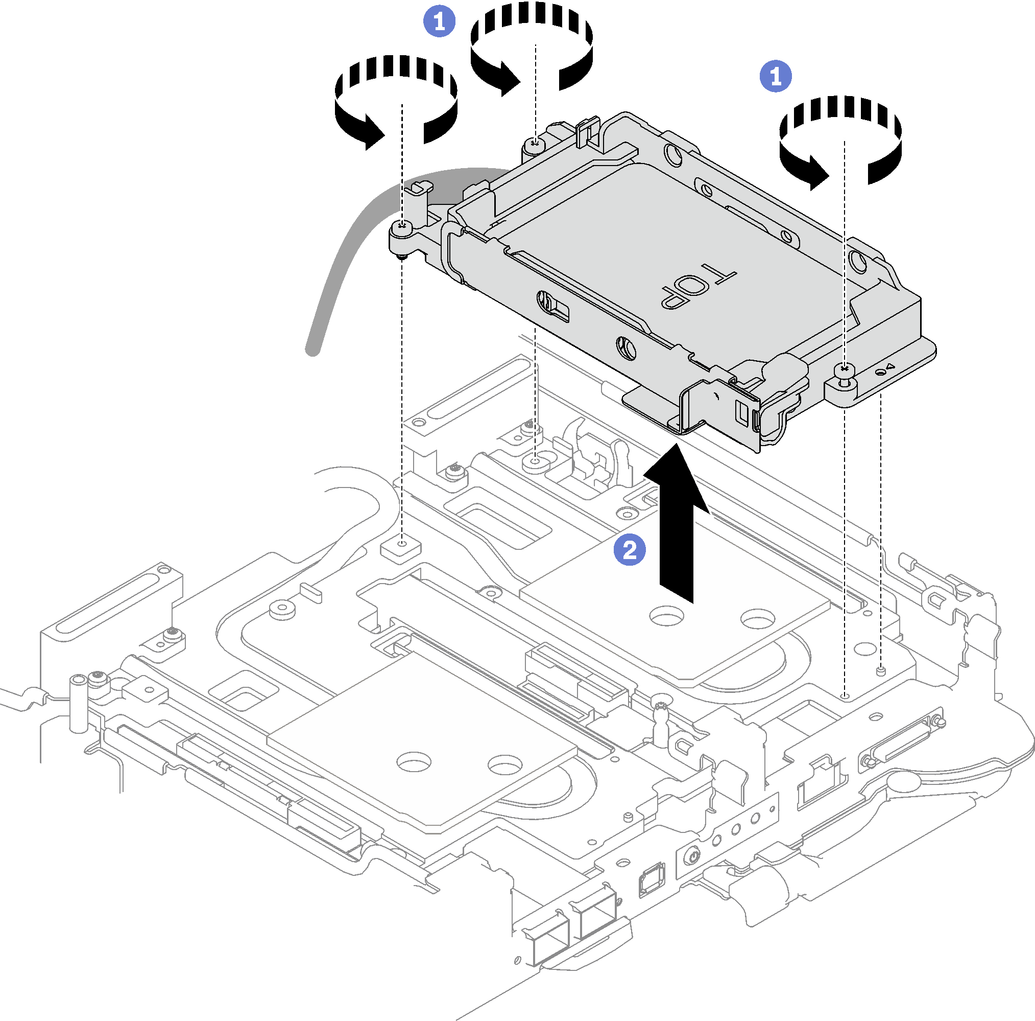 Figure 4. Two 7 mm drive cage assembly removal
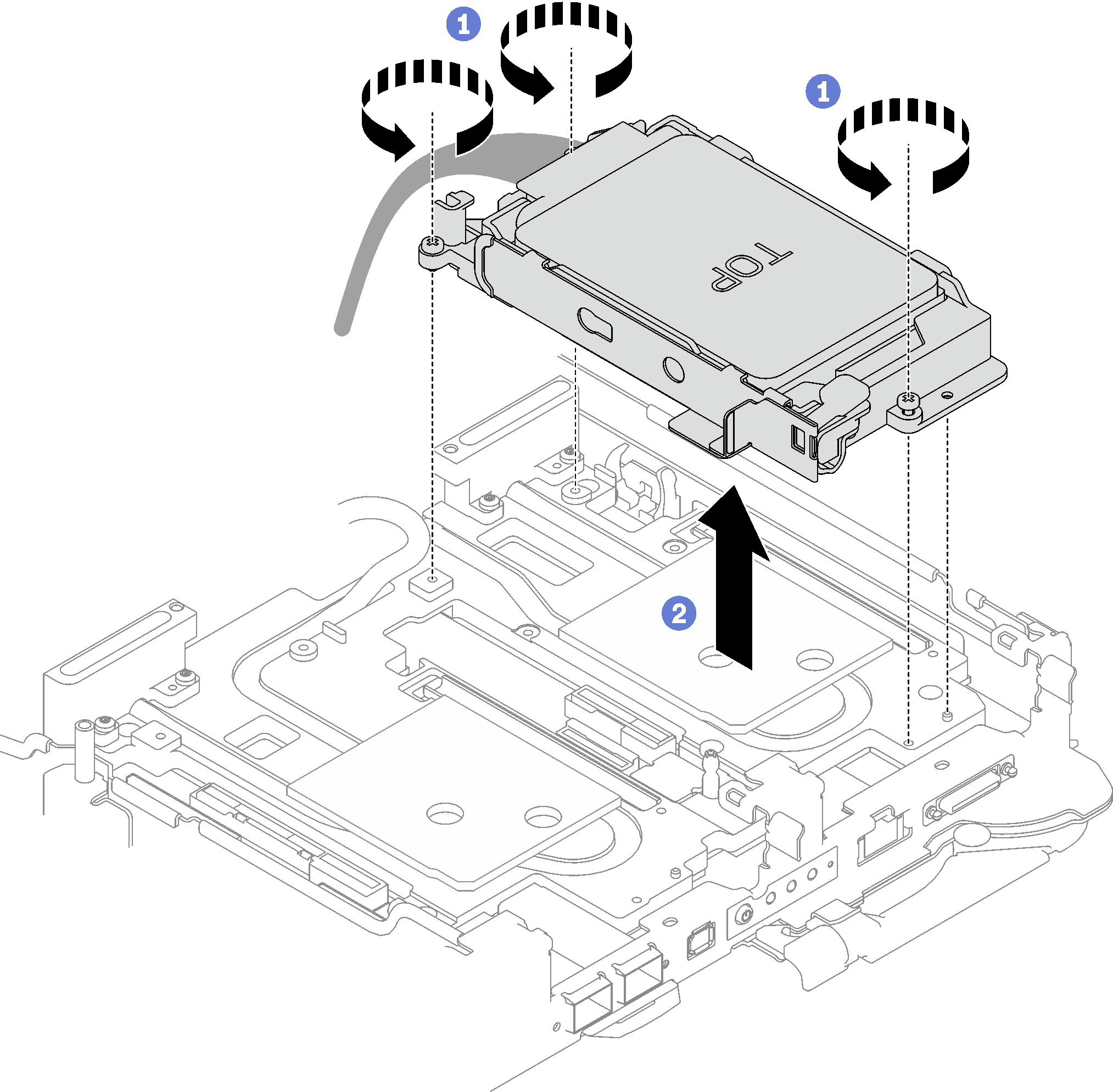 Figure 5. One 15 mm drive cage assembly removal
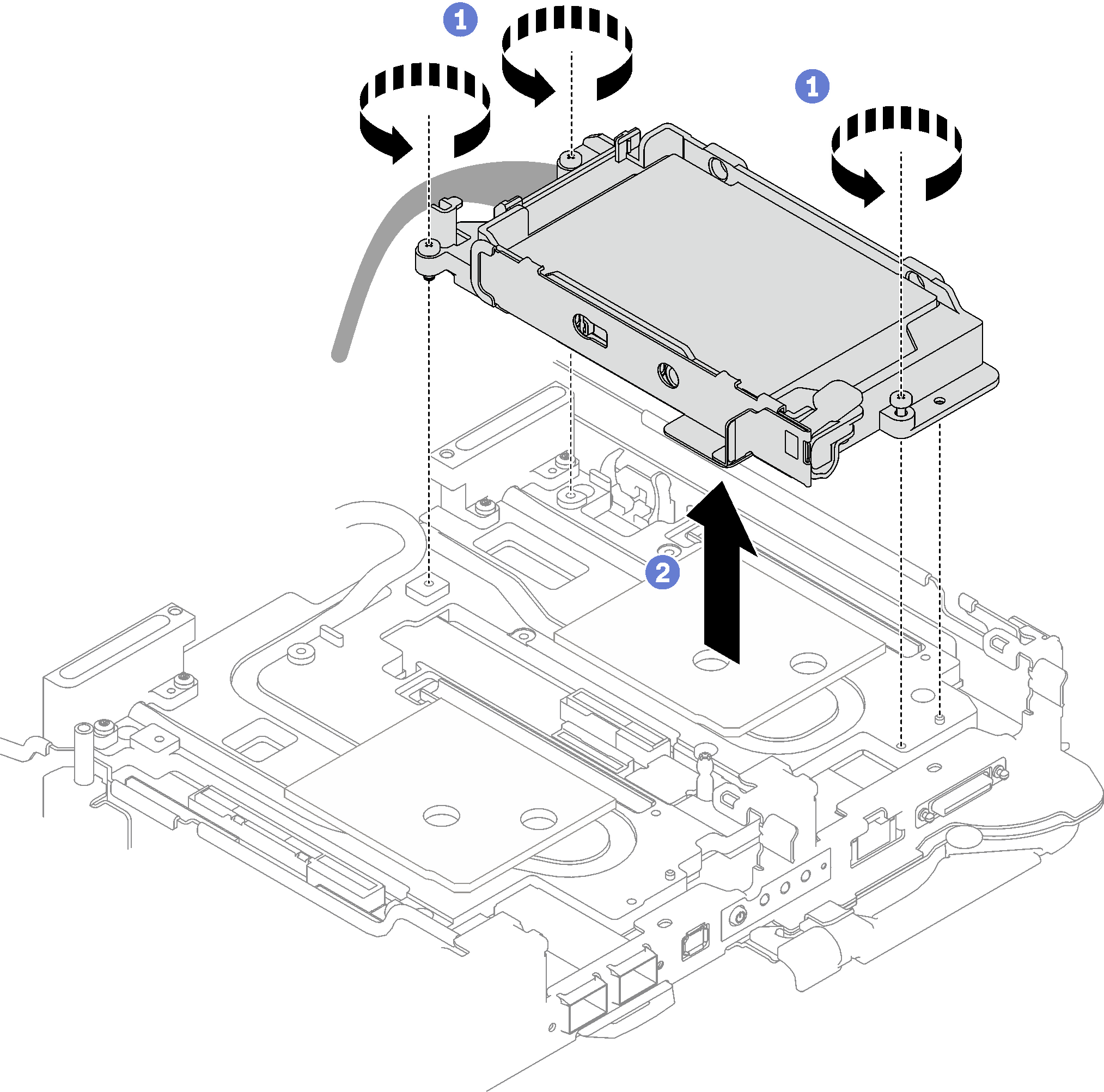
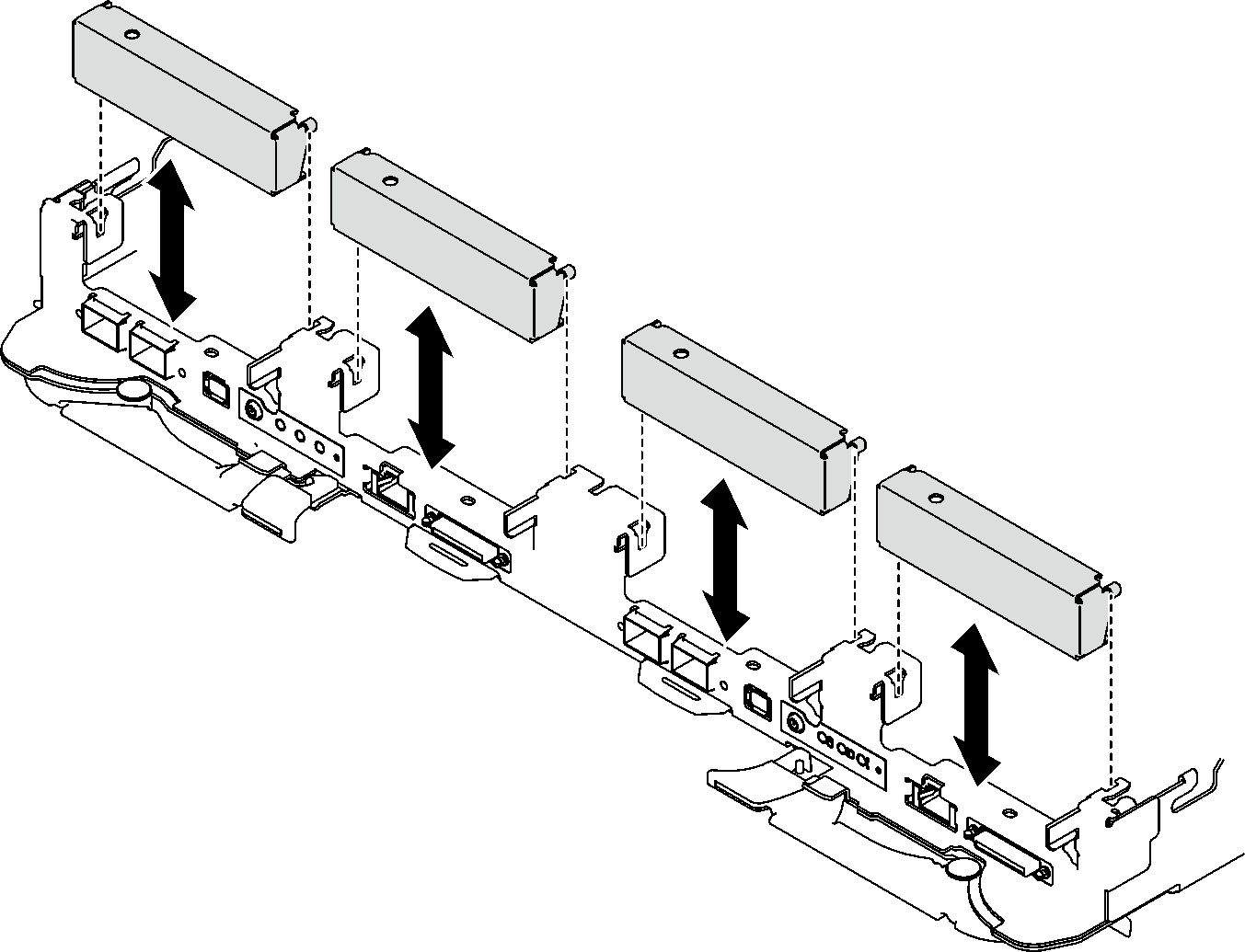
- If necessary, remove the blank bezel fillers.Figure 6. Blank bezel filler removal
After you finish
If you are instructed to return the component or optional device, follow all packaging instructions, and use any packaging materials for shipping that are supplied to you.
Demo video
Give documentation feedback