Install a drive cage assembly
Use this information to install a drive cage assembly.
About this task
Required tools
You may need the SD665 V3 Water Loop Gap Pad Kit to properly replace the component.
Read Installation Guidelines and Safety inspection checklist to ensure that you work safely.
You may need the Gap Pad Kit to perform this task.
To identify the gap pad/putty pad location and orientation, see:
Required Tools list in the following section.
Before replacing the gap pad/putty pad, gently clean the interface plate or the hardware surface with an alcohol cleaning pad.
Hold the gap pad/putty pad carefully to avoid deformation. Make sure no screw hole or opening is blocked by the gap pad/putty pad material.
Do not use expired putty pad. Check the expiry date on putty pad package. If the putty pads are expired, acquire new ones to properly replace them.
Go to Drivers and Software download website for ThinkSystem SD665 V3 to see the latest firmware and driver updates for your server.
Go to Update the firmware for more information on firmware updating tools.
Procedure
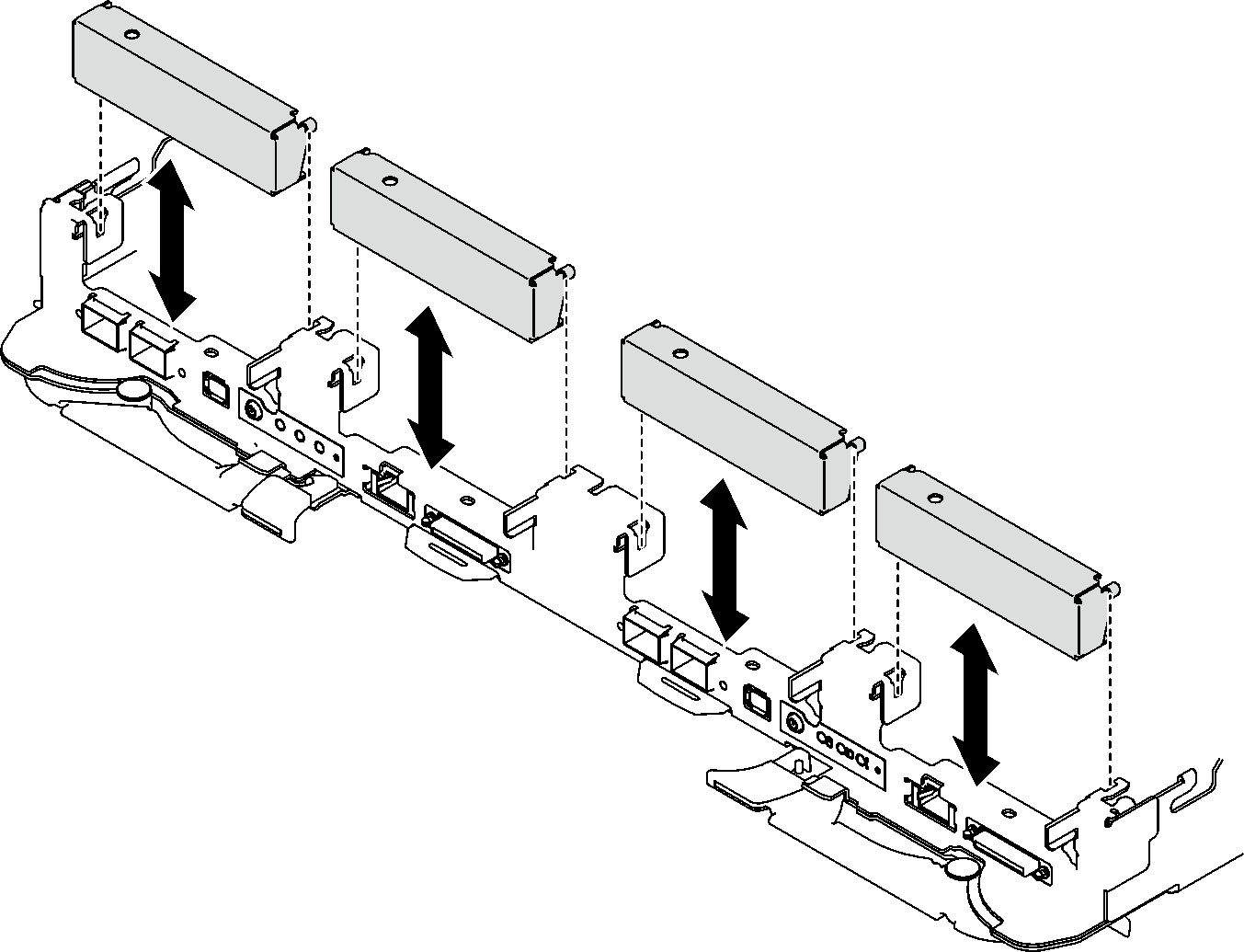
- Make sure the blank bezel fillers are installed. If not, install them to the node.Figure 1. Blank bezel filler installation
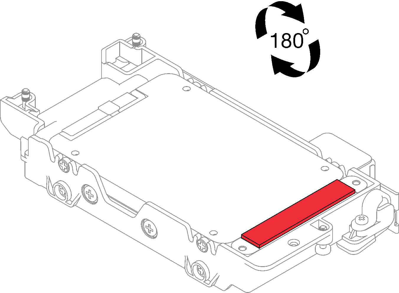
- If the gap pad located on the reverse side of the drive cage is damaged, missing, or fallen off the drive cage, replace it with a new one. Make sure to follow Gap pad/putty pad replacement guidelines.Figure 2. Gap pad location
- If the drive cage gap pad is damaged or missing, replace it with a new one. See the following for the gap pad location for each drive cage. Make sure to follow Gap pad/putty pad replacement guidelines.NoteAlign the gap pad with marking on water loop when attaching gap pad.Figure 3. Markings on water loop for gap pad alignment
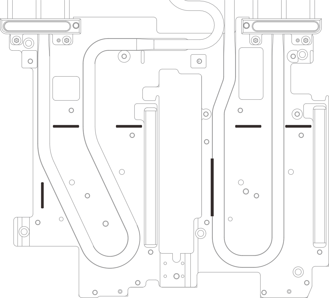 Figure 4. Replacing gap pad
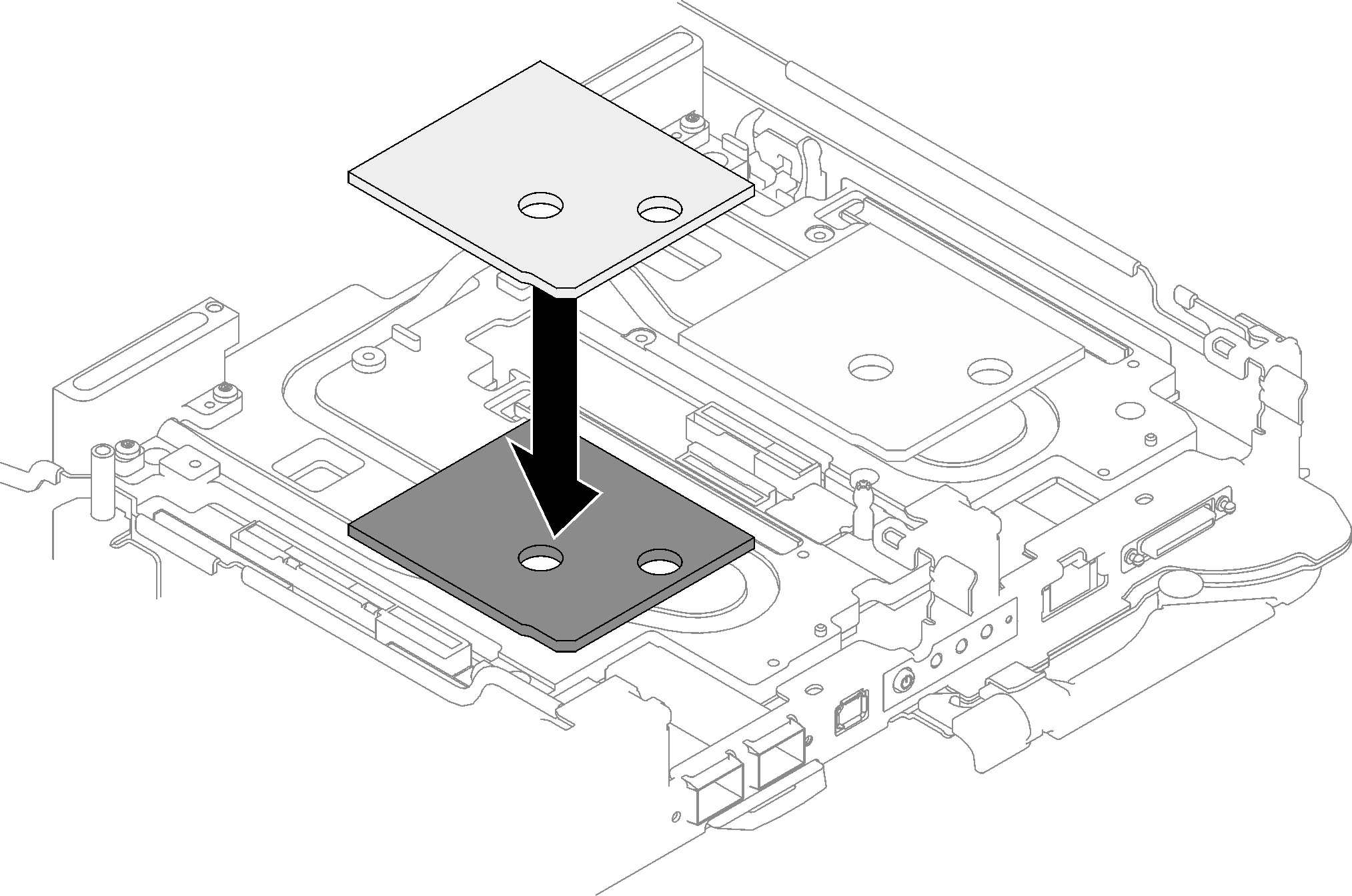 Figure 5. Gap pad locations
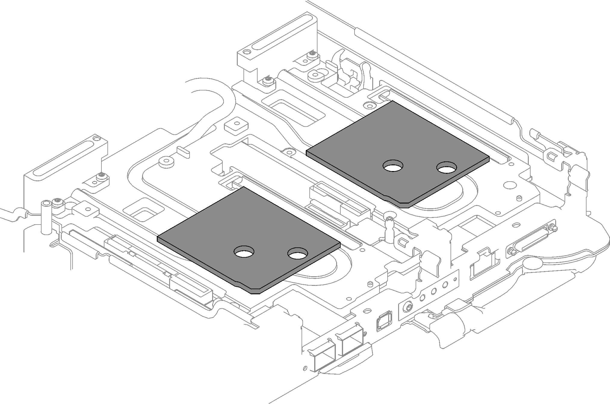
- Install the drive cage assembly.
 Install the drive assembly into the node.
 Secure the 3 screws.
NoteThe following illustration might differ slightly from your hardware, but the installation method is the same.Figure 6. One 7 mm drive cage assembly installation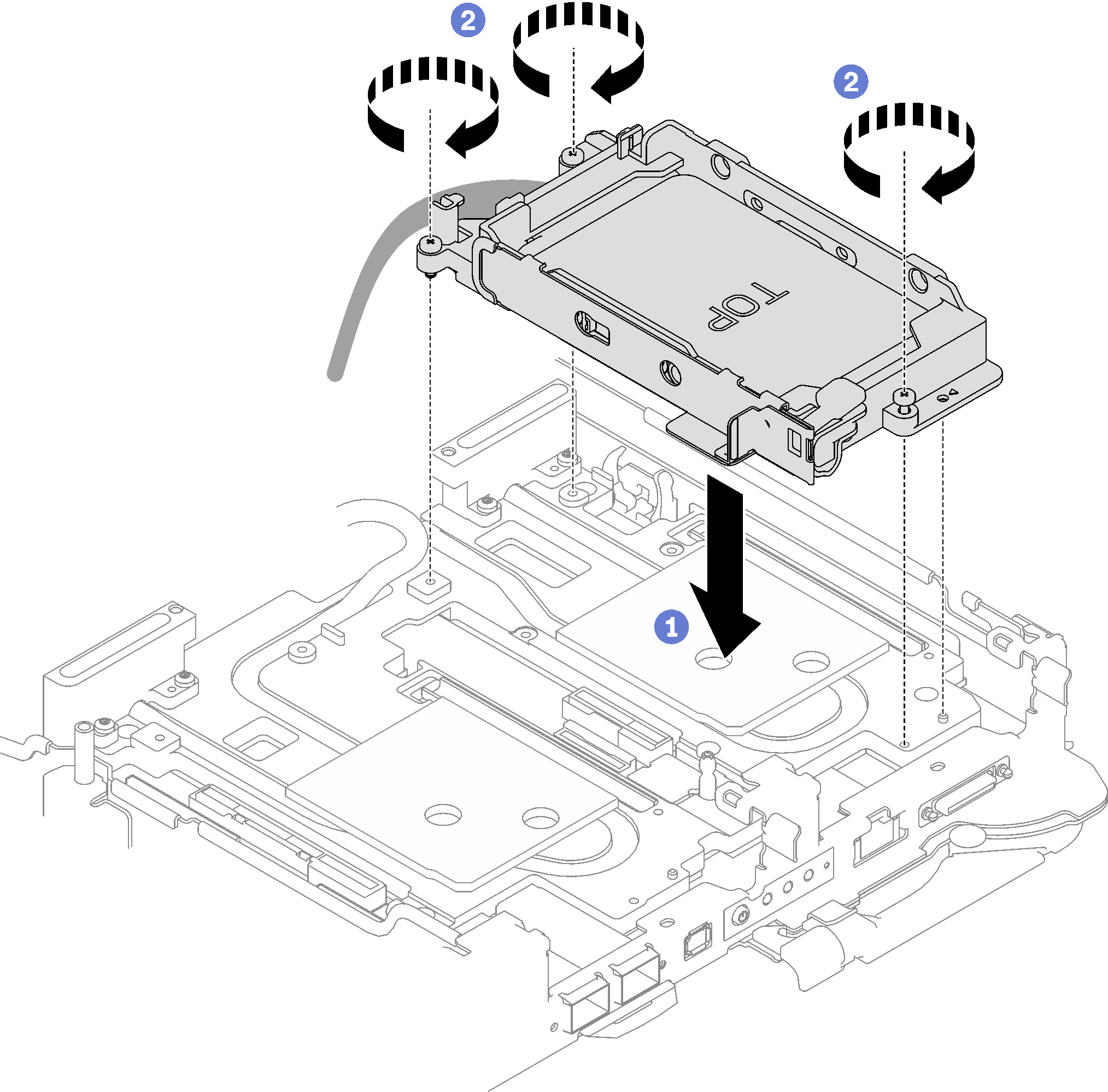 Figure 7. Two 7 mm drive cage assembly installation
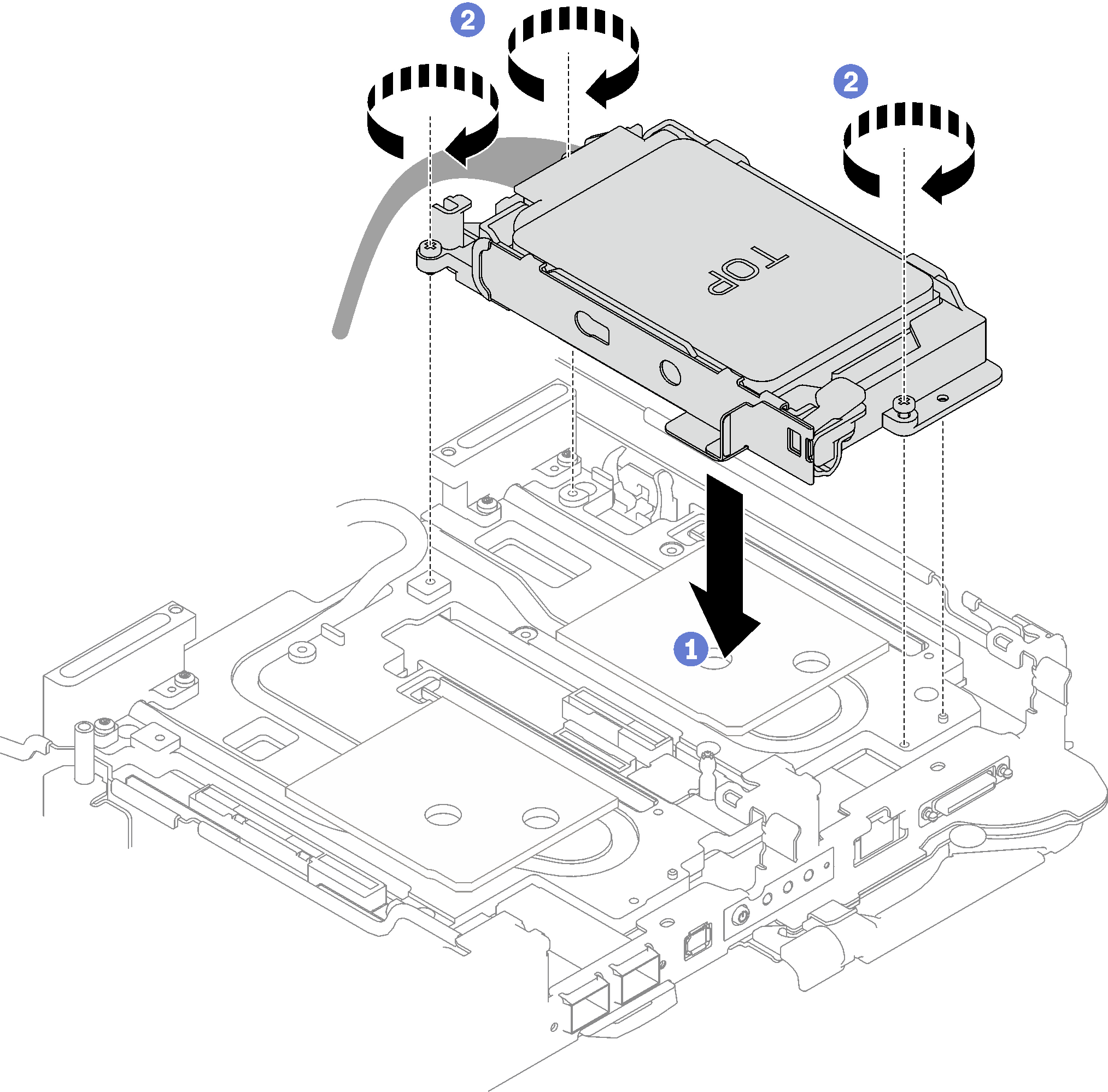 Figure 8. One 15 mm drive cage assembly installation
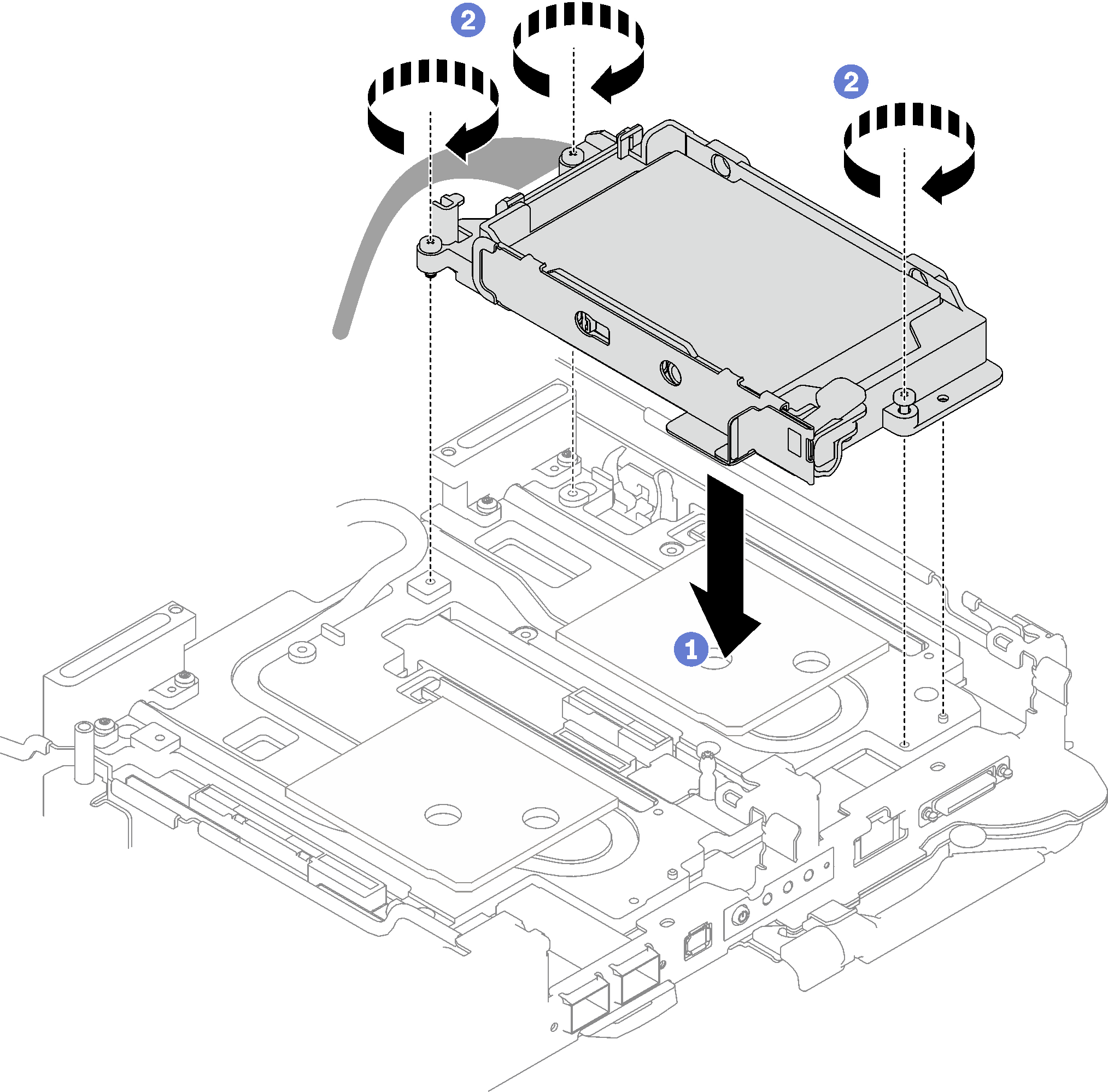
- Connect the drive assembly cable to the system board. Cable routing is different for SATA drives and NVMe drives. Follow the cable routing below according to the drive configuration in your system. For more information, see System-board connectors.Figure 9. Drive assembly cable routing for SATA drives
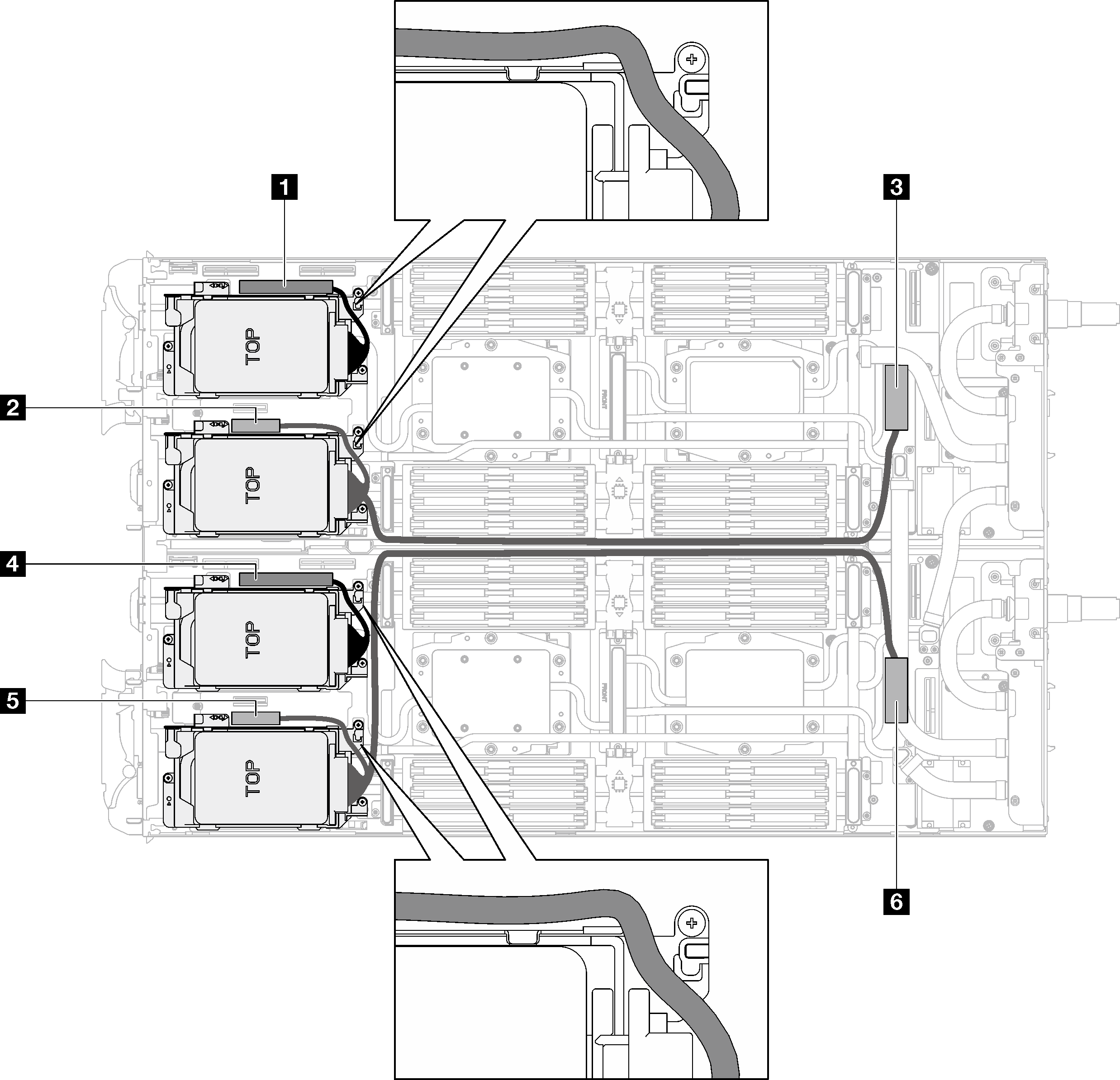
Table 1. Drive assembly cable routing for SATA drives System board connector Node 1 PCIe 2/SATA– drive 2/3 Left node 2 Power and sideband signal for drive bay 0/1 3 PCIe 1/SATA – drive 0/1 4 PCIe 2/SATA– drive 2/3 Right node 5 Power and sideband signal for drive bay 0/1 6 PCIe 1/SATA – drive 0/1 Figure 10. Drive assembly cable routing for all NVMe drives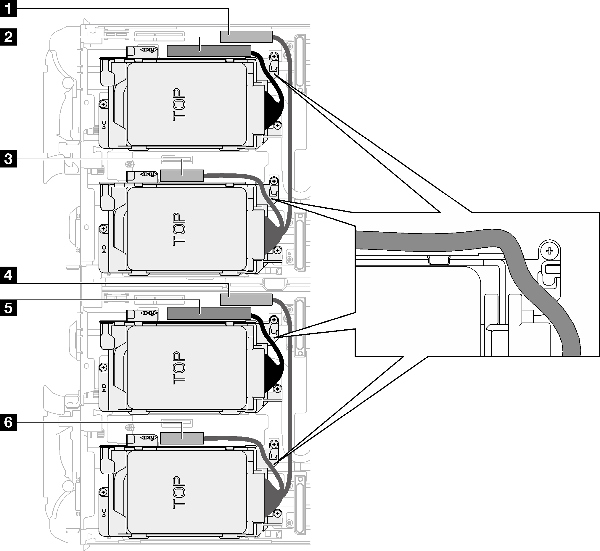
Table 2. Drive assembly cable routing for all NVMe drives System board connector Node 1 PCIe 3 – drive bay 0/1 (NVMe only) Left node 2 PCIe 2/SATA– drive 2/3 3 Power and sideband signal for riser 1 or drive bay 0/1 4 PCIe 3 – drive bay 0/1 (NVMe only) Right node 5 PCIe 2/SATA– drive 2/3 6 Power and sideband signal for riser 1 or drive bay 0/1
Install the cross braces. See Install the cross braces.
Install the tray cover. See Install the tray cover.
Install the tray into the enclosure. See Install a DWC tray in the enclosure.
- Connect all required external cables to the solution.NoteUse extra force to connect QSFP cables to the solution.
Check the power LED on each node to make sure it changes from fast blink to slow blink to indicate all nodes are ready to be powered on.
Demo video