Install a drive
Use this information to install a drive.
About this task
Required tools
You may need the SD665 V3 Water Loop Gap Pad Kit to properly replace the component.
Read Installation Guidelines and Safety inspection checklist to ensure that you work safely.
You may need the Gap Pad Kit to perform this task.
To identify the gap pad/putty pad location and orientation, see:
Required Tools list in the following section.
Before replacing the gap pad/putty pad, gently clean the interface plate or the hardware surface with an alcohol cleaning pad.
Hold the gap pad/putty pad carefully to avoid deformation. Make sure no screw hole or opening is blocked by the gap pad/putty pad material.
Do not use expired putty pad. Check the expiry date on putty pad package. If the putty pads are expired, acquire new ones to properly replace them.
Procedure
- For installing one 7 mm or 15 mm drive only, complete the following steps.
 Find the cable with its plugger marked as SSD 0/2, and connect it to the drive.
 Flip the drive over.
 Install the drive into the bottom of the drive cage and make sure it is secured in place.
Figure 1. 7 mm drive installation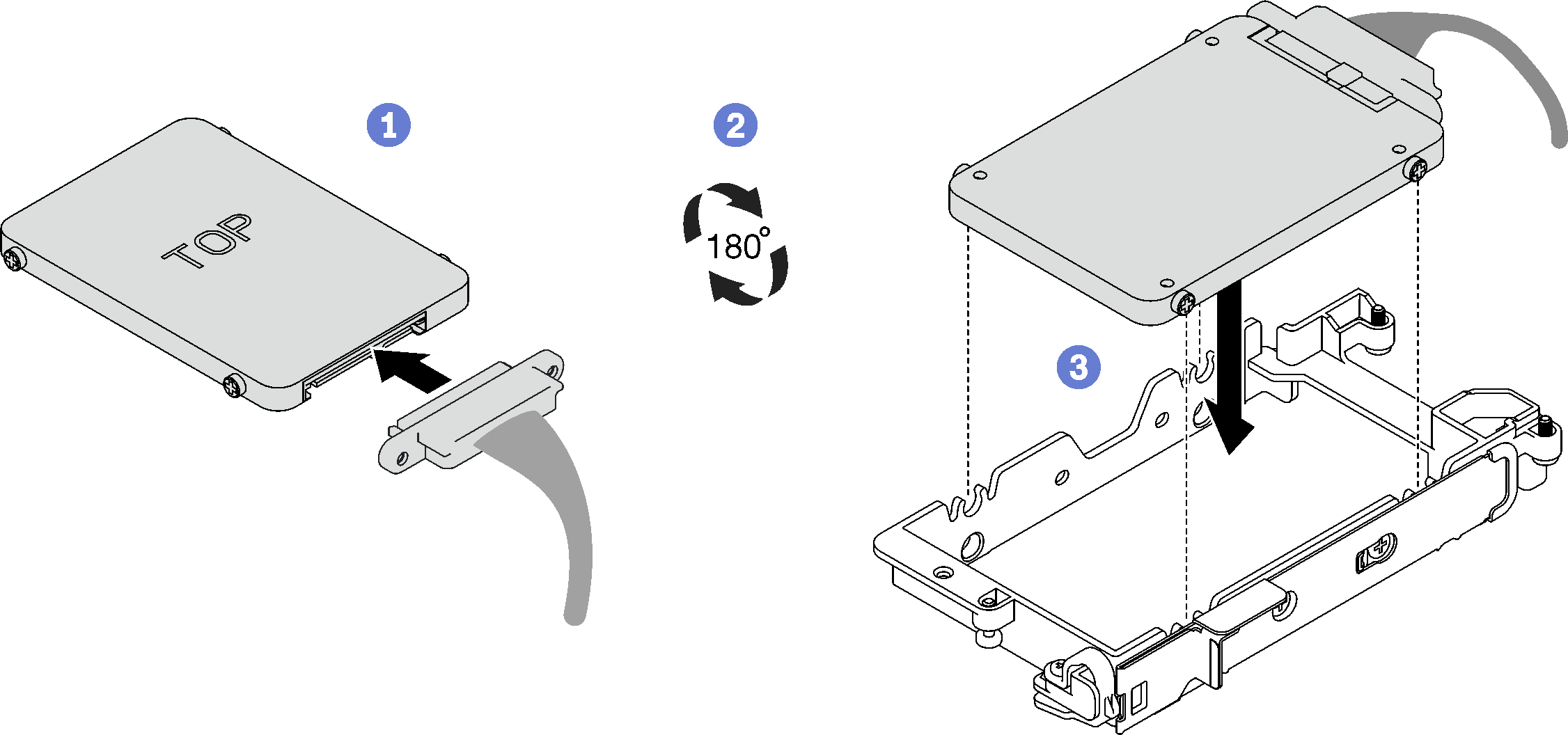 Figure 2. 15 mm drive installation
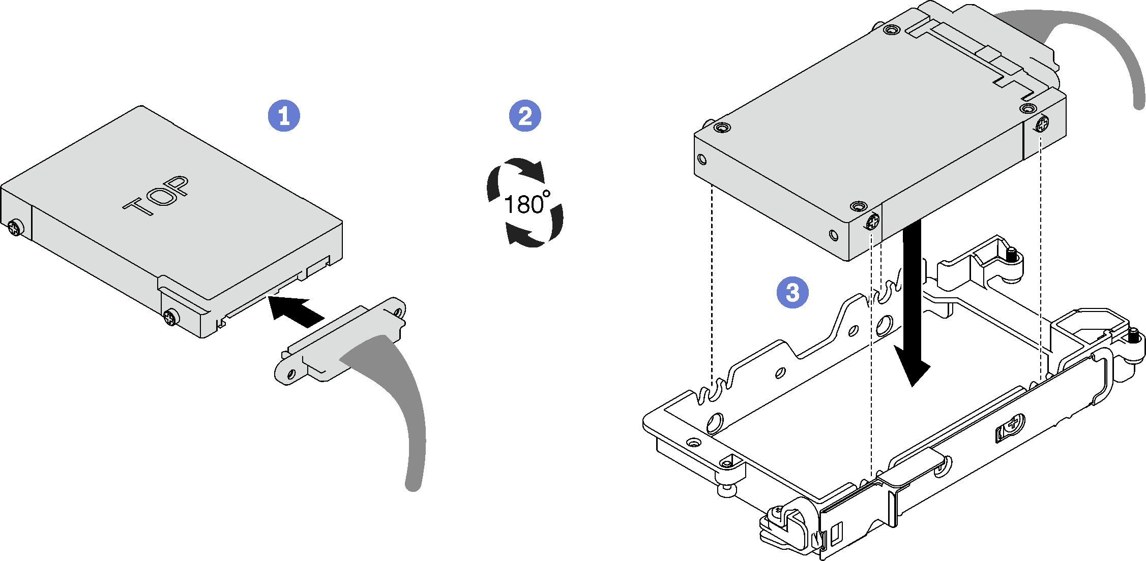 NoteSecure the unconnected cable plugger on top side of the drive cage.Figure 3. Securing the unplugged cable plugger
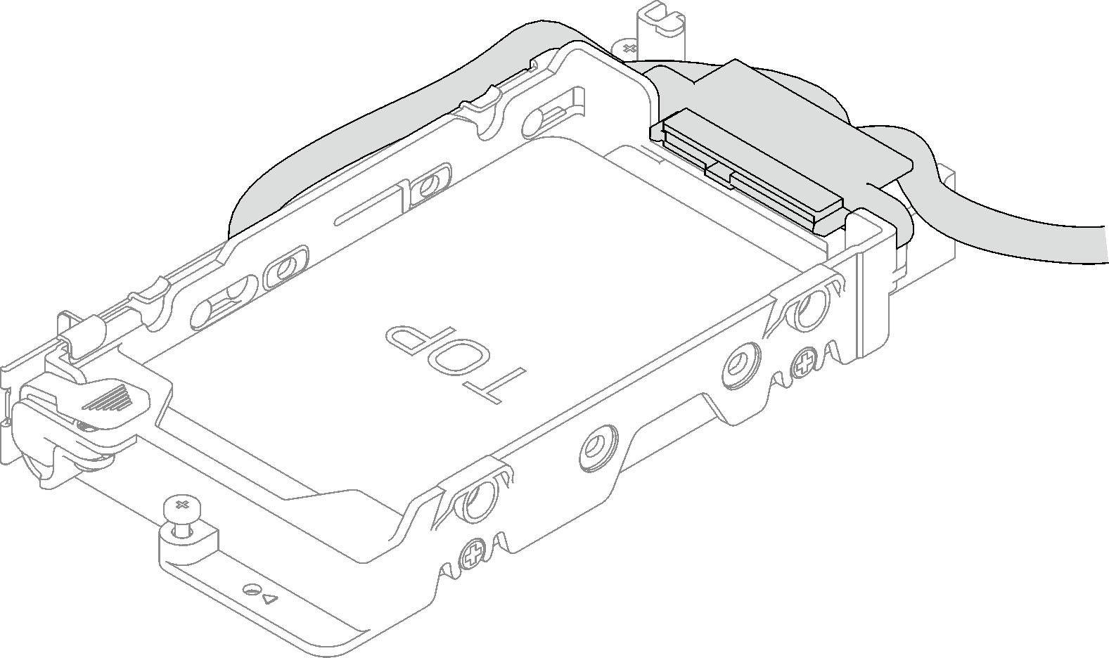
- For installing two 7 mm drives, complete the following steps.
If removed, install the conduction plate into the bottom of the drive cage and secure it with four screws.
If the gap pad located on the reverse side of the drive is damaged, missing, or fallen off the conduction late, replace it with a new one. Make sure to follow the Gap pad/putty pad replacement guidelines.
NoteMake sure the metal tab is in the unlocked position.Figure 4. Conduction plate installation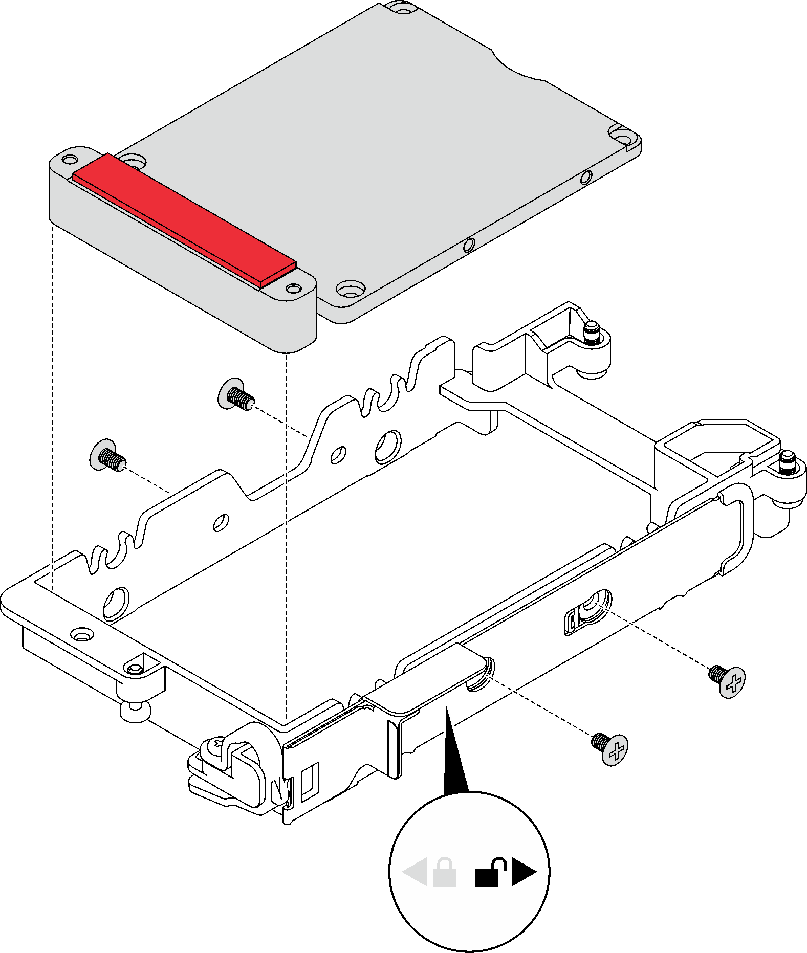
- Install the lower drive.
- Find the cable with its plugger marked as SSD 0/2, and connect it to the drive.
- Flip the drive over.
- Install the drive into the bottom of the drive cage and make sure it is secured in place.
Figure 5. Lower drive installation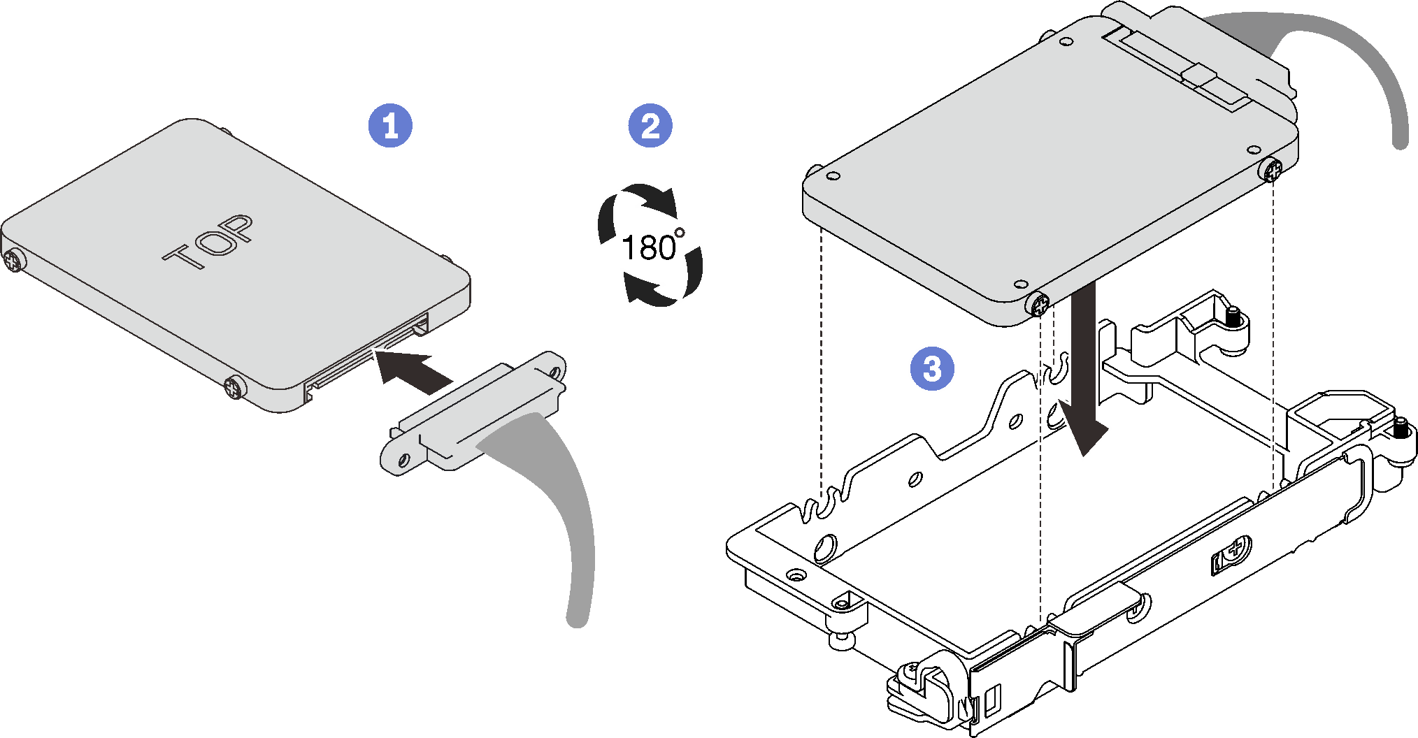
- Install the upper drive.
- Find the cable with its plugger marked as SSD 1/3, and connect it to the drive. Then, pivot the drive into the top of the drive cage as shown.
- Push and hold the release latch.
- Slide the metal tab to the locked position.
Figure 6. Upper drive installation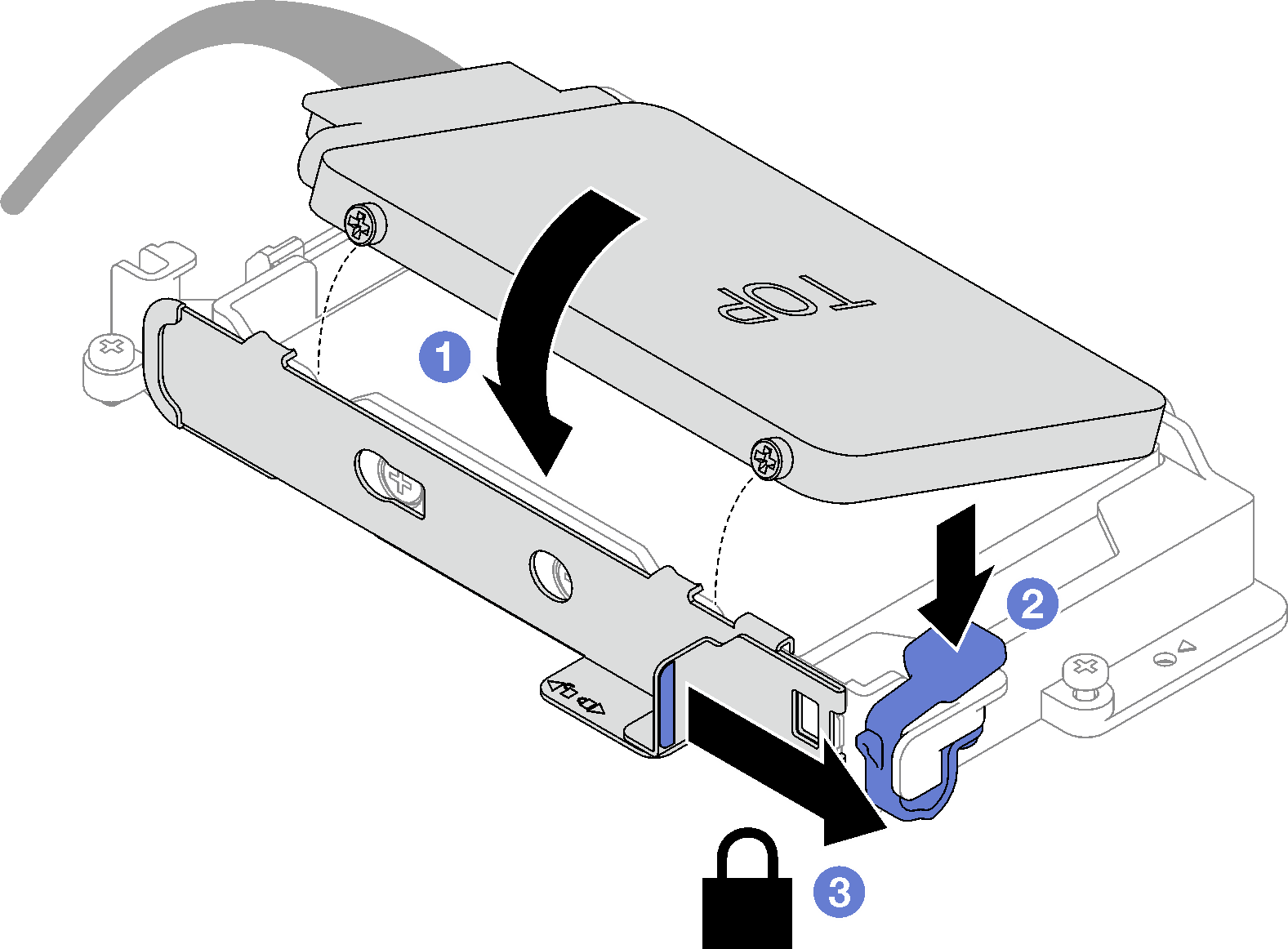
Install the drive cage. See Install a drive cage assembly.
Install the cross braces. See Install the cross braces.
Install the tray cover. See Install the tray cover.
Install the tray into the enclosure. See Install a DWC tray in the enclosure.
- Connect all required external cables to the solution.NoteUse extra force to connect QSFP cables to the solution.
Check the power LED on each node to make sure it changes from fast blink to slow blink to indicate all nodes are ready to be powered on.
Demo video