Remove the system board assembly
Use this information to remove the system board assembly.
- Read the following sections to ensure that you work safely.
Record all system configuration information, such as Lenovo XClarity Controller IP addresses, vital product data, and the machine type, model number, serial number, Universally Unique Identifier, and asset tag of the server.
If the server has SED installed, maintain a backup of SED AK. See Backup the Self Encryption Drive Authentication Key (SED AK) for more details.
Use the Lenovo XClarity Essentials OneCLI to save the system configuration to external media.
Log on XCC Web GUI and backup config to external media.
Download the XCC Service Data to external media.
Turn off the server. Disconnect the power cords and all external cables (see Power off the server).
Remove the node from the enclosure if needed (see Remove a node).
Remove the top cover (see Remove the top cover).
Procedure
- Remove the two screws on the bottom of the server.Figure 1. Screws removal
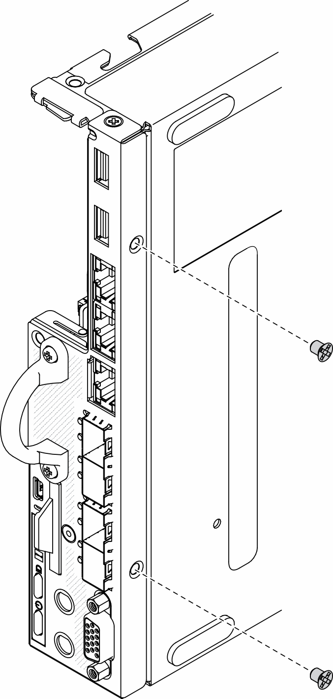
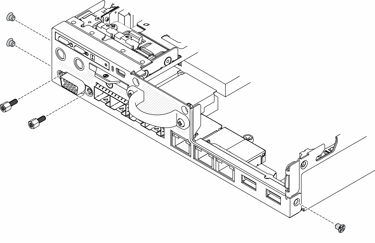
- Remove the three screws on the sides of the server, and remove the two screws that secure VGA connector.Figure 2. Screws removal
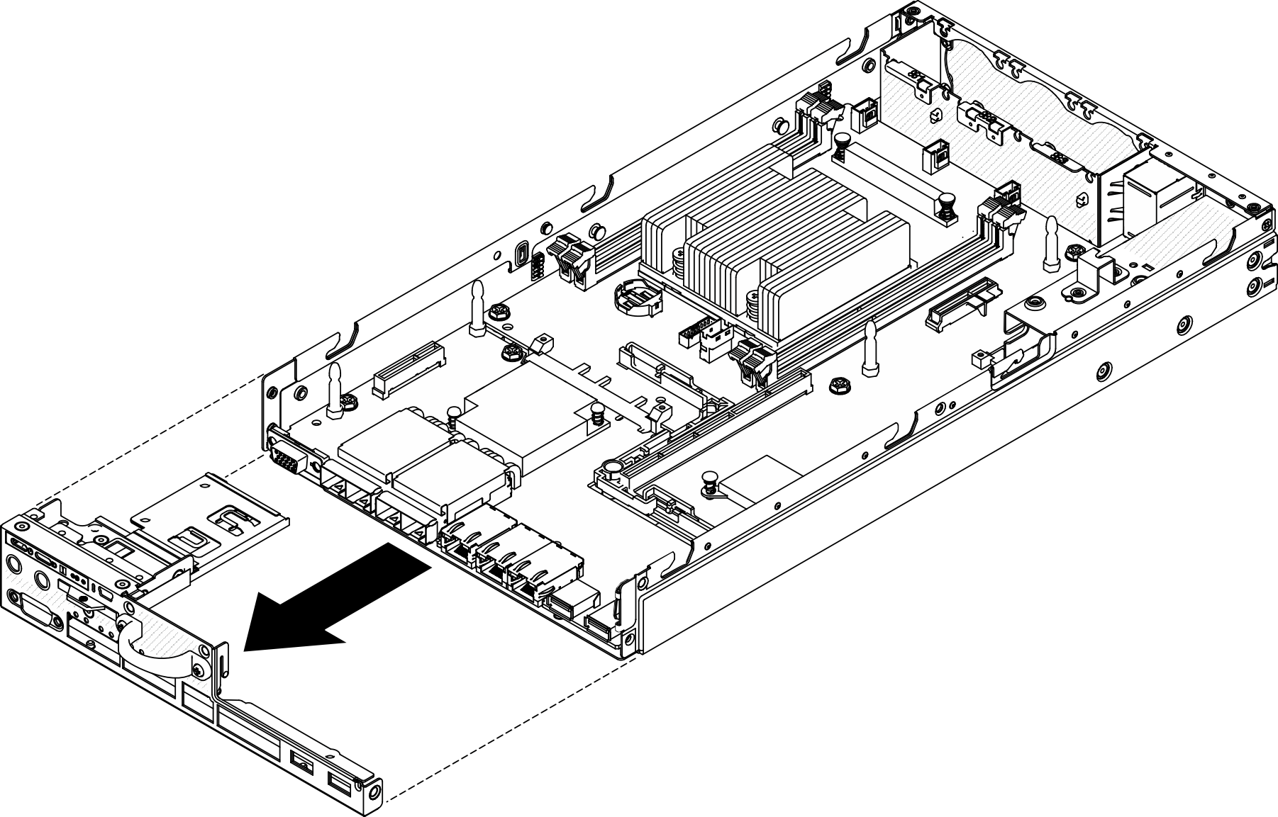
- Remove the front operator panel by pulling it out from the server.Figure 3. Front operator panel removal
- Remove the six screws that secure the LOM package.Figure 4. LOM package removal

- Slightly pull the LOM package forward, and lift it up at an angle as shown to remove it from the server.Figure 5. LOM package removal
 NoteWireless enabled LOM package and 10G SFP+ LOM package are removed with the same method.
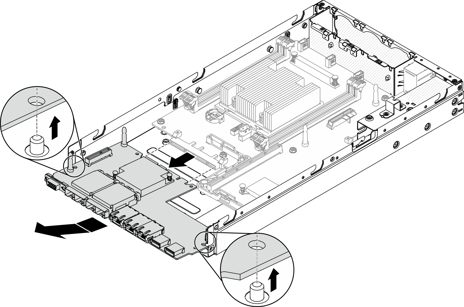
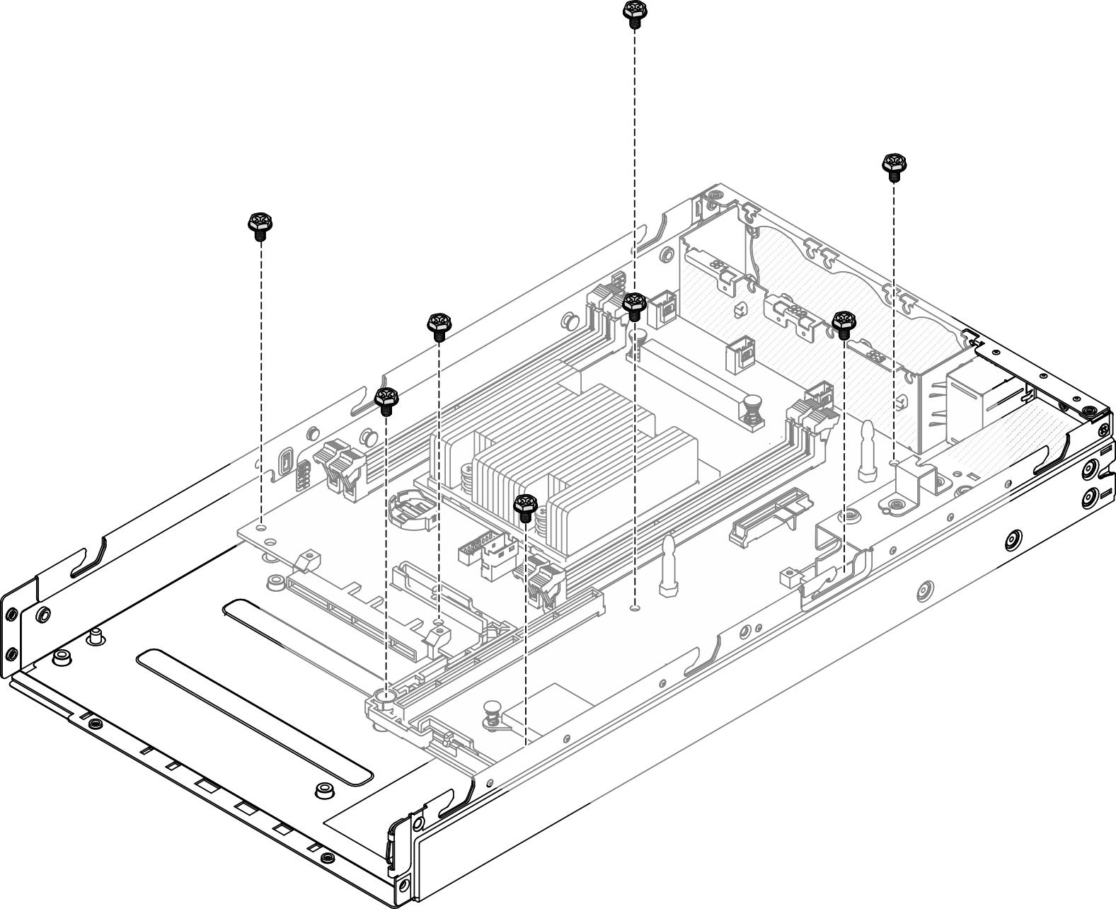
 - Remove the eight screws that secure the system board.Figure 6. System board removal
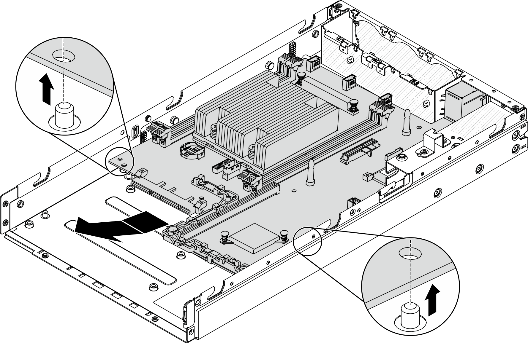
- Pull the system board forward and lift it up slightly to remove it from the guide pins.Figure 7. System board removal
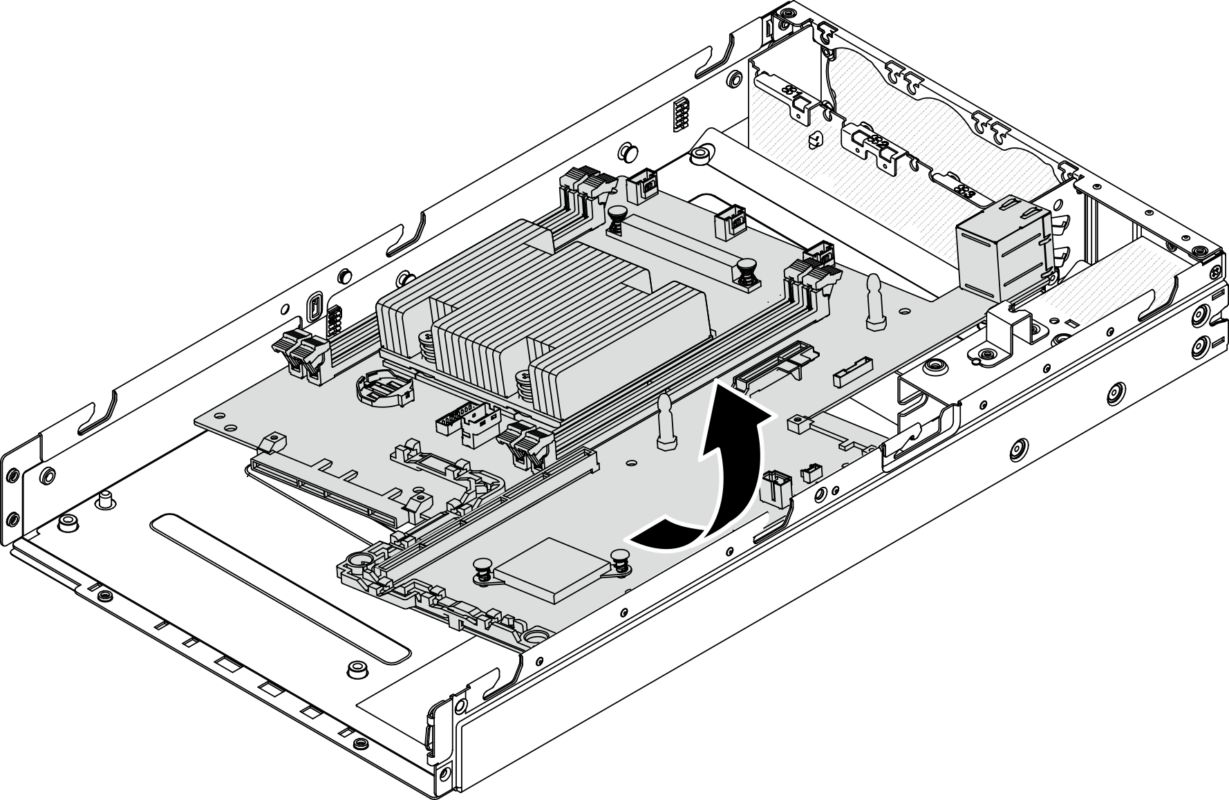
- Lift the system board toward the side of the server as shown to remove it from the server.Figure 8. System board removal
If you are instructed to return the defective component, please package the part to prevent any shipping damage. Reuse the packaging the new part arrived in and follow all packaging instructions.
Demo video