Install the system board assembly
Use this information to install the system board assembly.
- Read the following sections to ensure that you work safely.
Touch the static-protective package that contains the component to any unpainted metal surface on the server; then, remove it from the package and place it on a static-protective surface.
If an insulating pull tab is under the CMOS battery on the replacement system board, remove it.
Figure 1. Insulating pull tab removal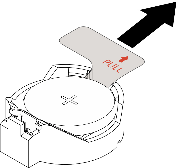
Procedure
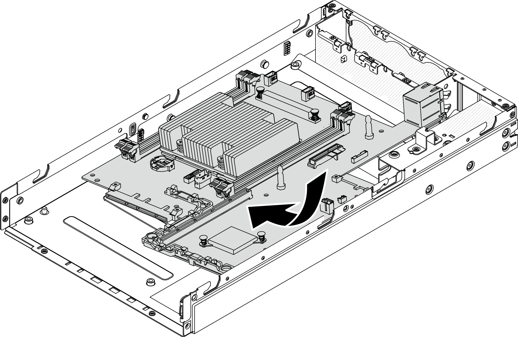
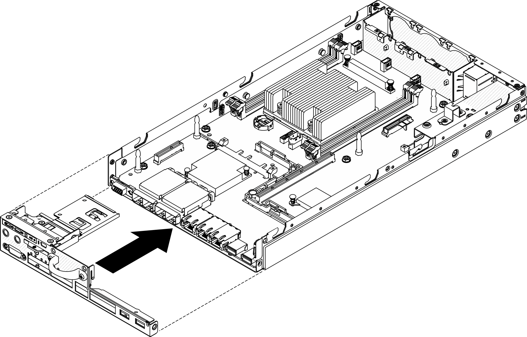
- Insert the system board into the chassis with an angle as shown.Figure 2. System board installation
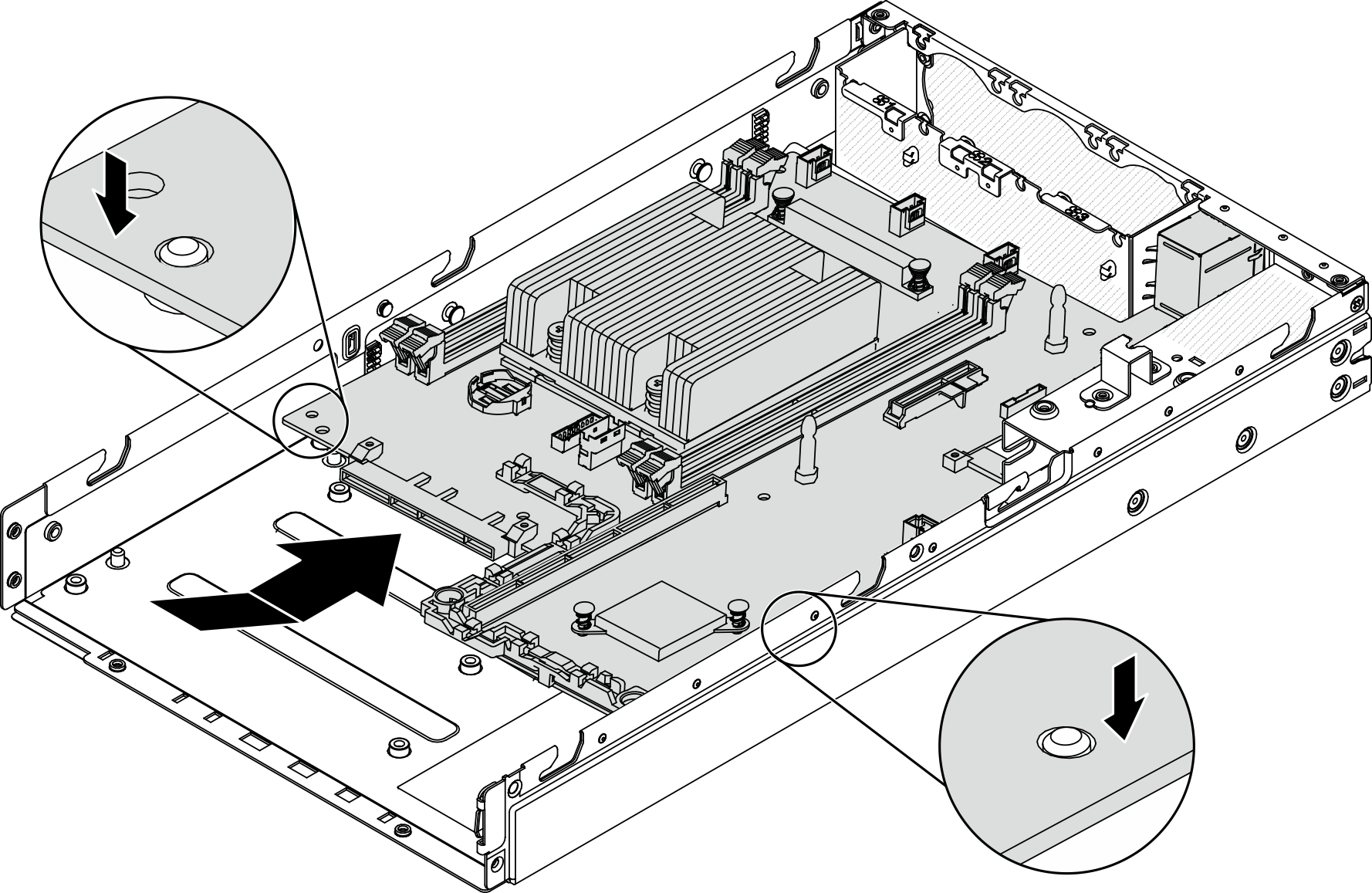
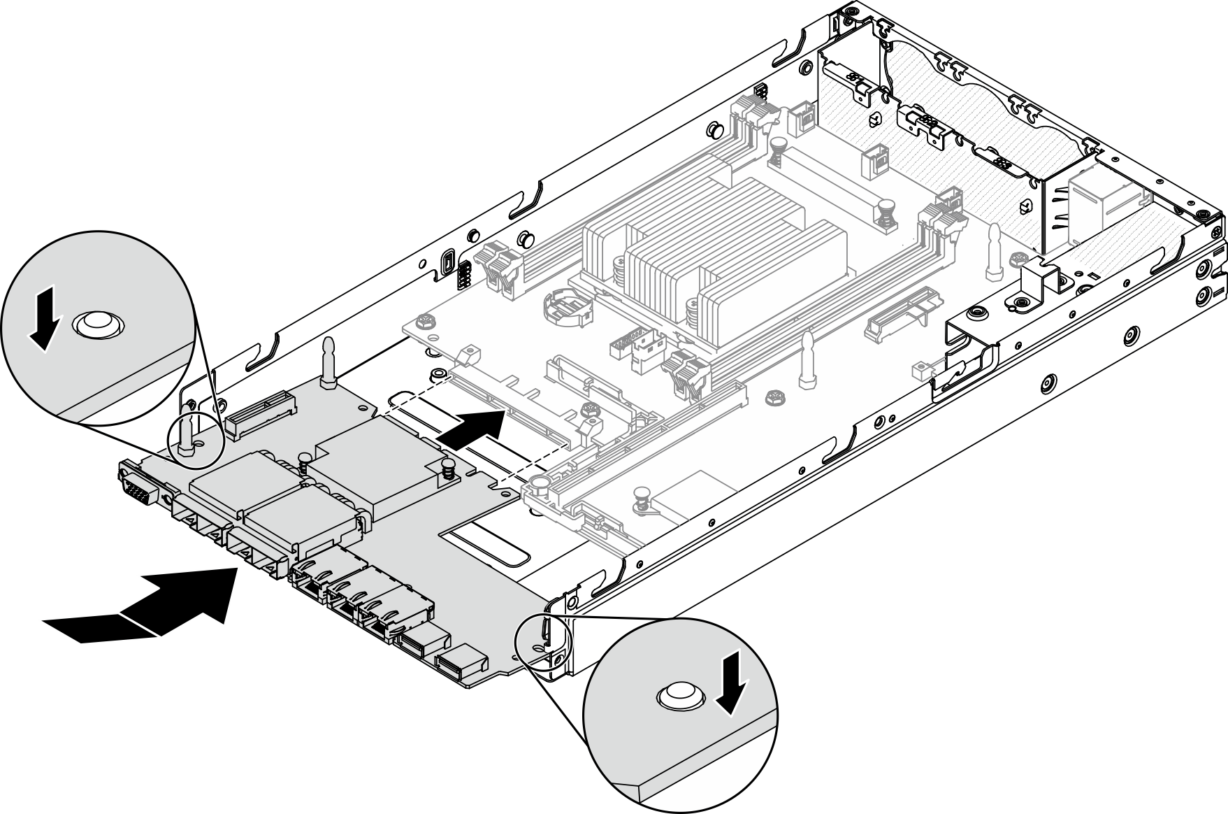
- Push the system board into the server and seat the system board onto the guide pins.Figure 3. System board installation
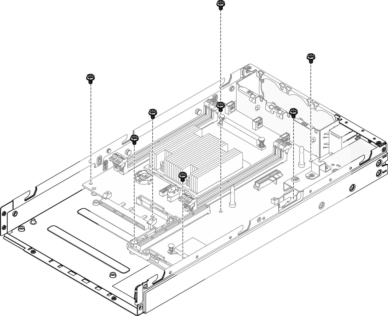
- Install the eight screws to secure the system board.Figure 4. System board installation
- Insert the LOM package into the server at an angle as shown; then, seat the LOM package onto the guide pins.NoteWireless enabled LOM package and 10G SFP+ LOM package are installed with the same method.Figure 5. LOM package installation
- Install the six screws to secure the LOM package.Figure 6. LOM package installation

- Align the front operator panel with the chassis and insert the panel onto the front of the server.Figure 7. Front operator panel installation
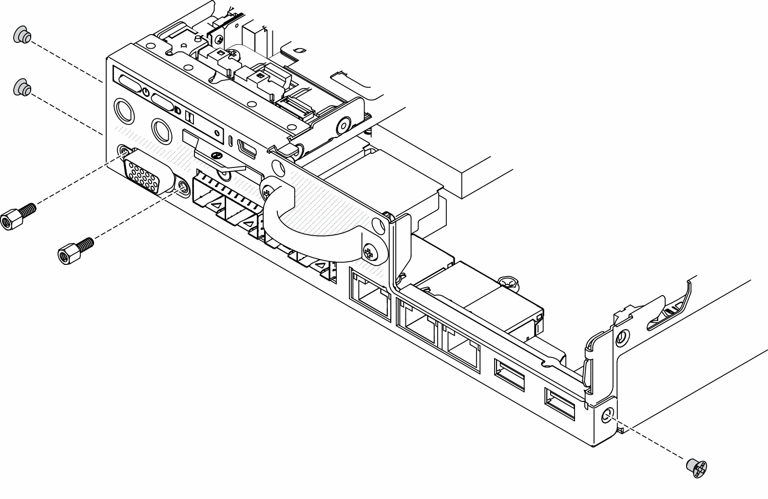
- Install the two screws that secure VGA connector, and install the three screws on the sides of the server.Figure 8. Screws installation
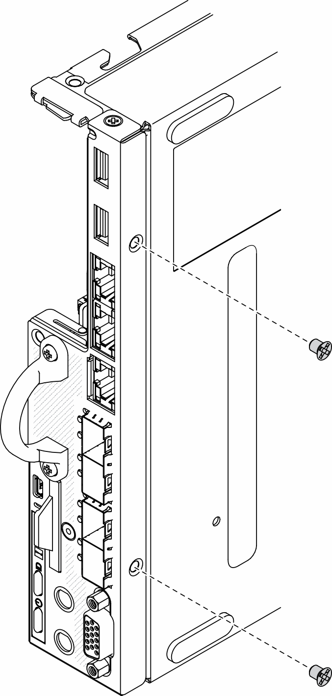
- Install the two screws on the bottom of the server.Figure 9. Screws installation
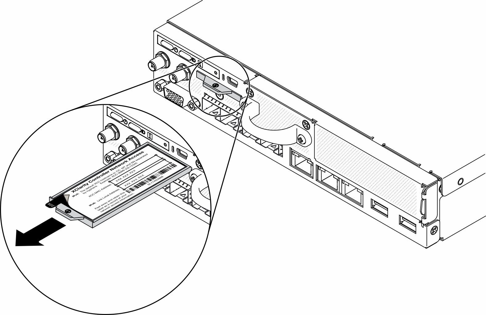
- Peel away the XClarity Controller network access label on the processor heat sink and attach it to the network access tag on the front of the server.Figure 10. Location of the network access tag
After you install the system board, complete the following steps:
Install the top cover onto the server (see Install the top cover).
Install the node if needed (see Install a node).
Reconnect power cords and all external cables.
Reconfigure the server and reset the system date and time.
Update the machine type and serial number with new vital product data (VPD). Use the Lenovo XClarity Provisioning Manager to update the machine type and serial number. See Update the machine type and serial number.
NoteIf the node is to be installed in an E1 Enclosure (1U 2-node), change the vital product data (VPD) for proper operation.See Change the VPD for E1 Enclosure configuration (trained technician only).If the server has SED installed, recover the SED AK. See Backup the Self Encryption Drive Authentication Key (SED AK) for more details.
Recover the FoD key if needed.
Update the public key. See the
Update Device Key
section of ThinkShield Edge Mobile Management Application User Guide or ThinkShield Key Vault Portal Web Application User Guide in ThinkEdge Security for more details.For ThinkSystem SE350 with Security Pack, re-activate the system. See Activate the system for more information.
Enable TPM. See Enable TPM.
Optionally, enable Secure Boot. See Enable UEFI Secure Boot.
Demo video