Remove the PCIe riser assemblies and adapters
See this topic to learn how to remove the PCIe riser assemblies and adapters.
About this task
Procedure
Remove riser assemblies with half-length adapters
- Loosen the two captive screws; then, lift the riser assembly to remove it from the chassis.Figure 1. Removing PCIe riser 1
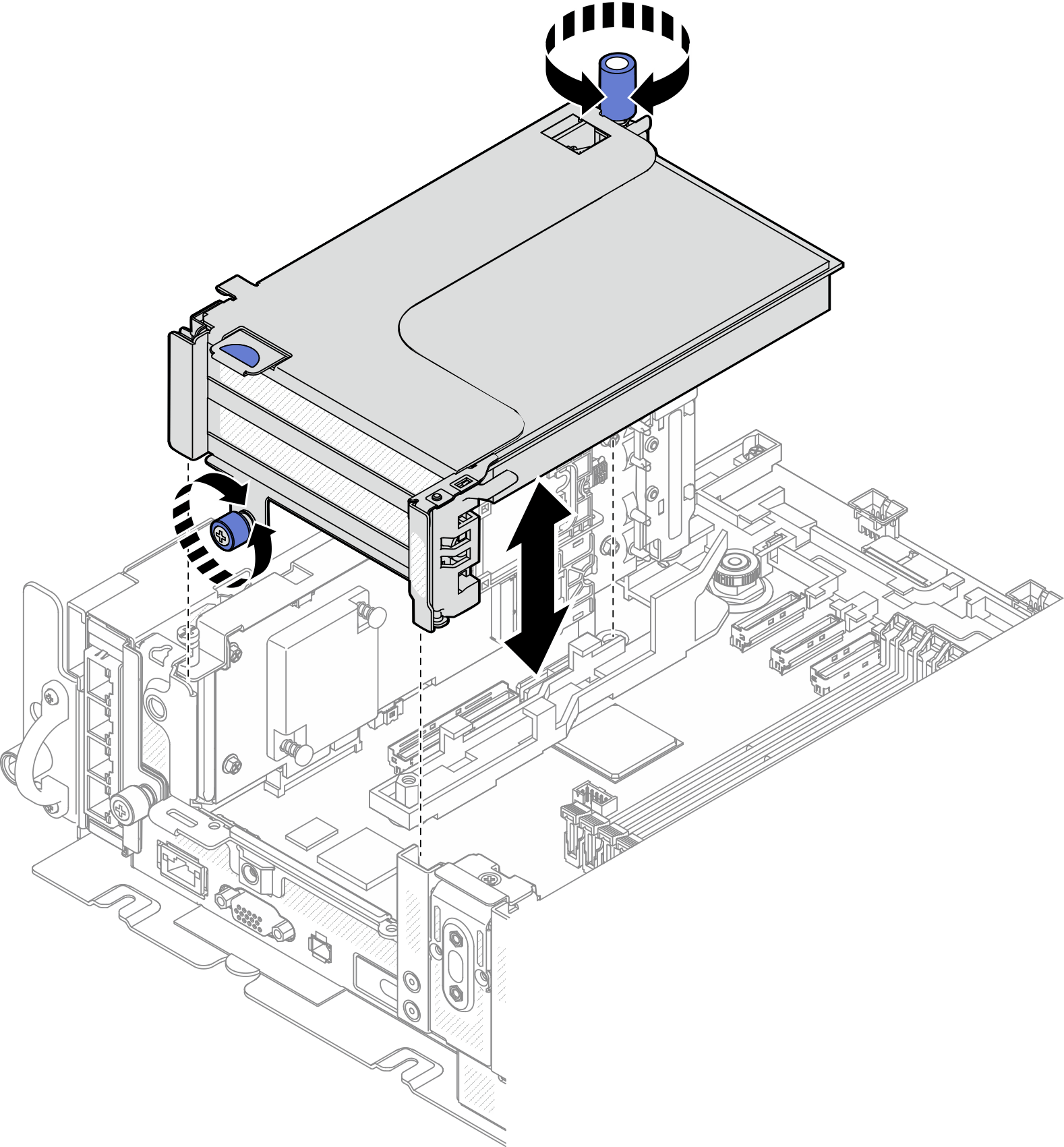 Figure 2. Removing PCIe riser 2
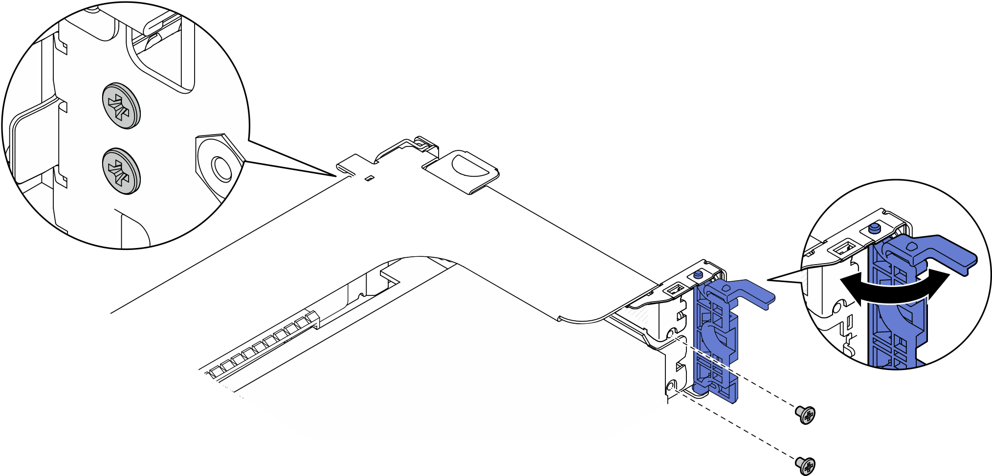
- Open the retainer, and remove the screws that secure the adapter to the riser.Figure 3. Removing the retaining screws
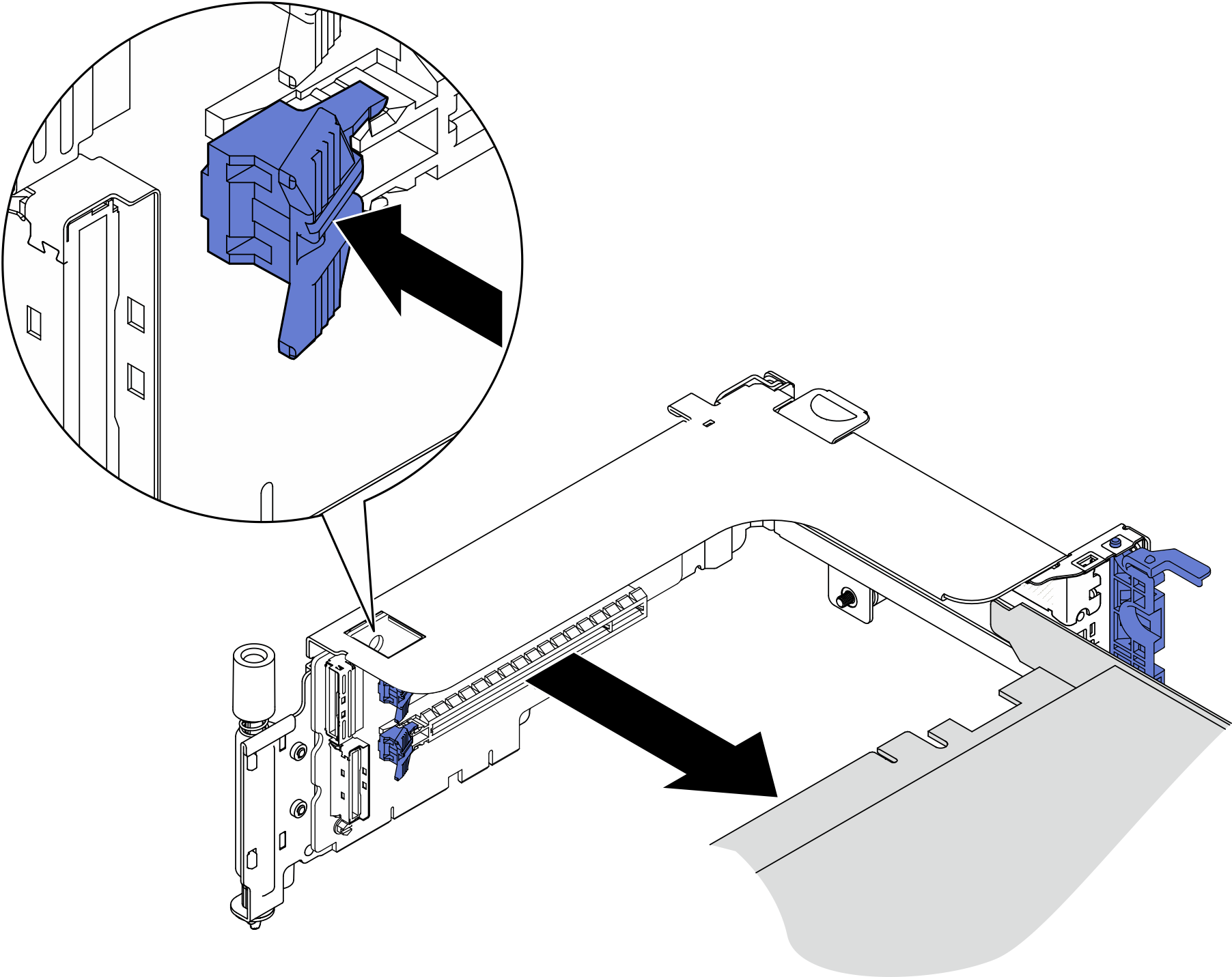
- Press on the latch to disengage the adapter from the riser, and remove the adapter.Figure 4. Removing an adapter from the riser
Remove PCIe riser 2 with AnyBay drive cage
Procedure
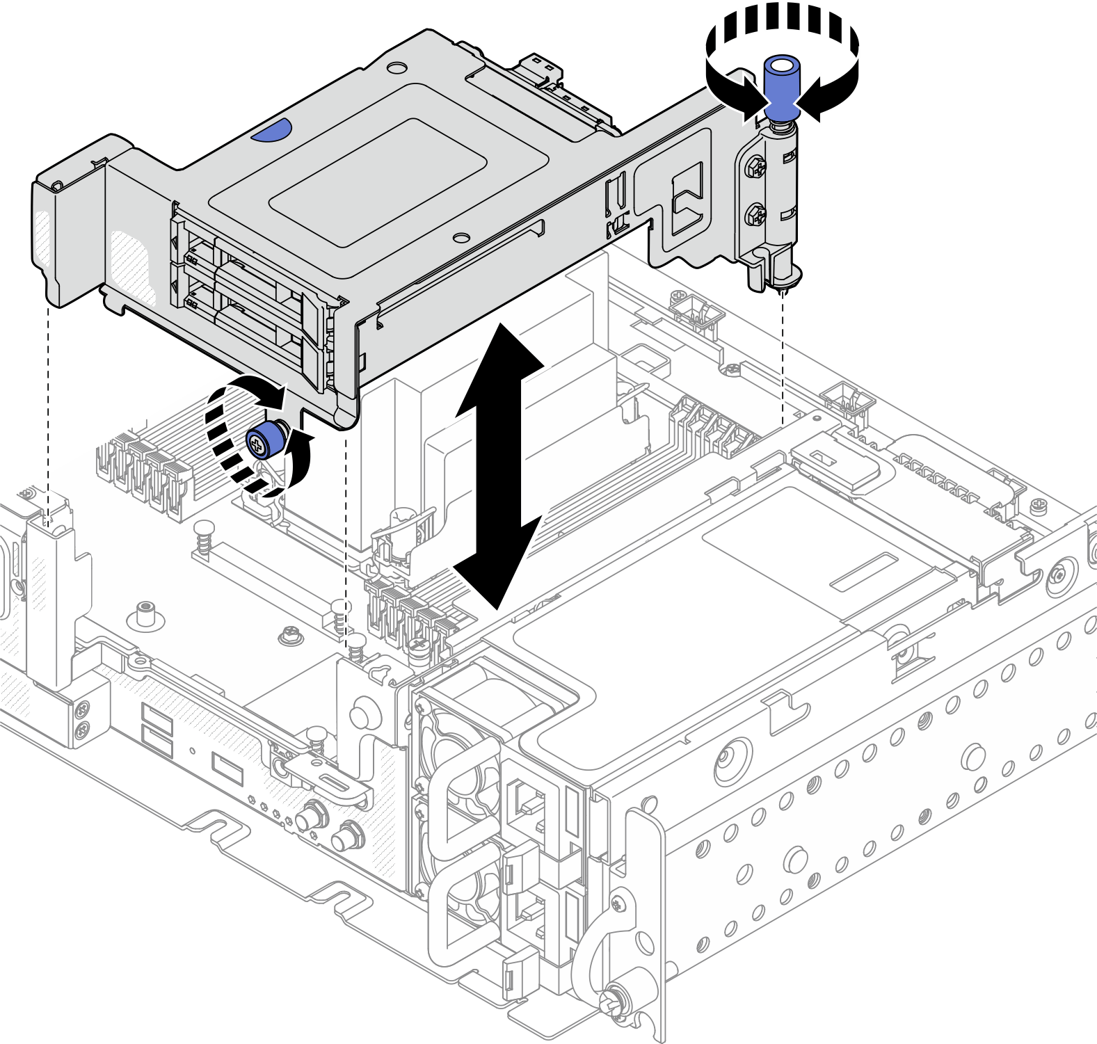
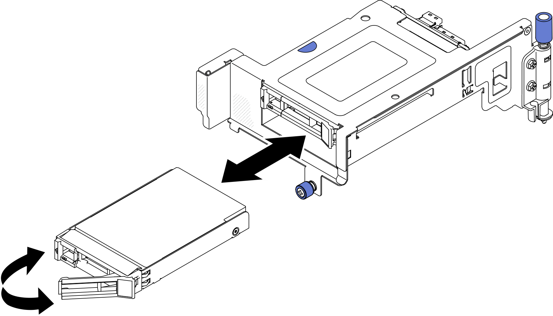
- Loosen the two captive screws; then, lift the riser assembly to remove it from the chassis.Figure 5. Removing PCIe riser 2 with drive cage
- Gently rotate the release latch away to unlock the drive handle; then, grasp and pull the handle to remove the drive from the drive bay.Figure 6. Removing the hot-swap drives
Remove PCIe riser assemblies with full-length adapters
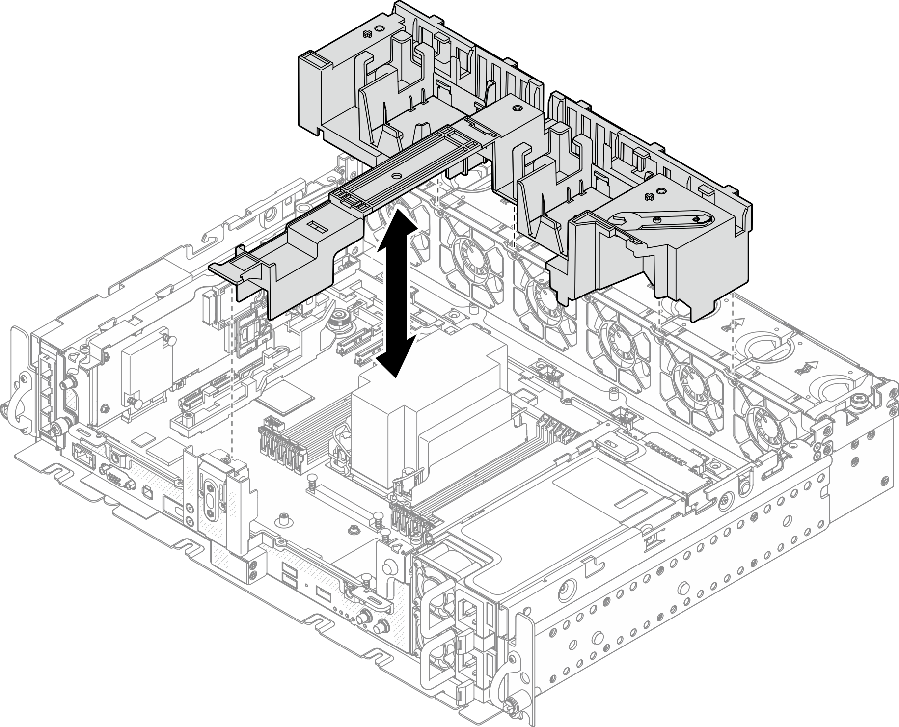
- Remove the supporting bracket.Figure 7. Removing the supporting bracket
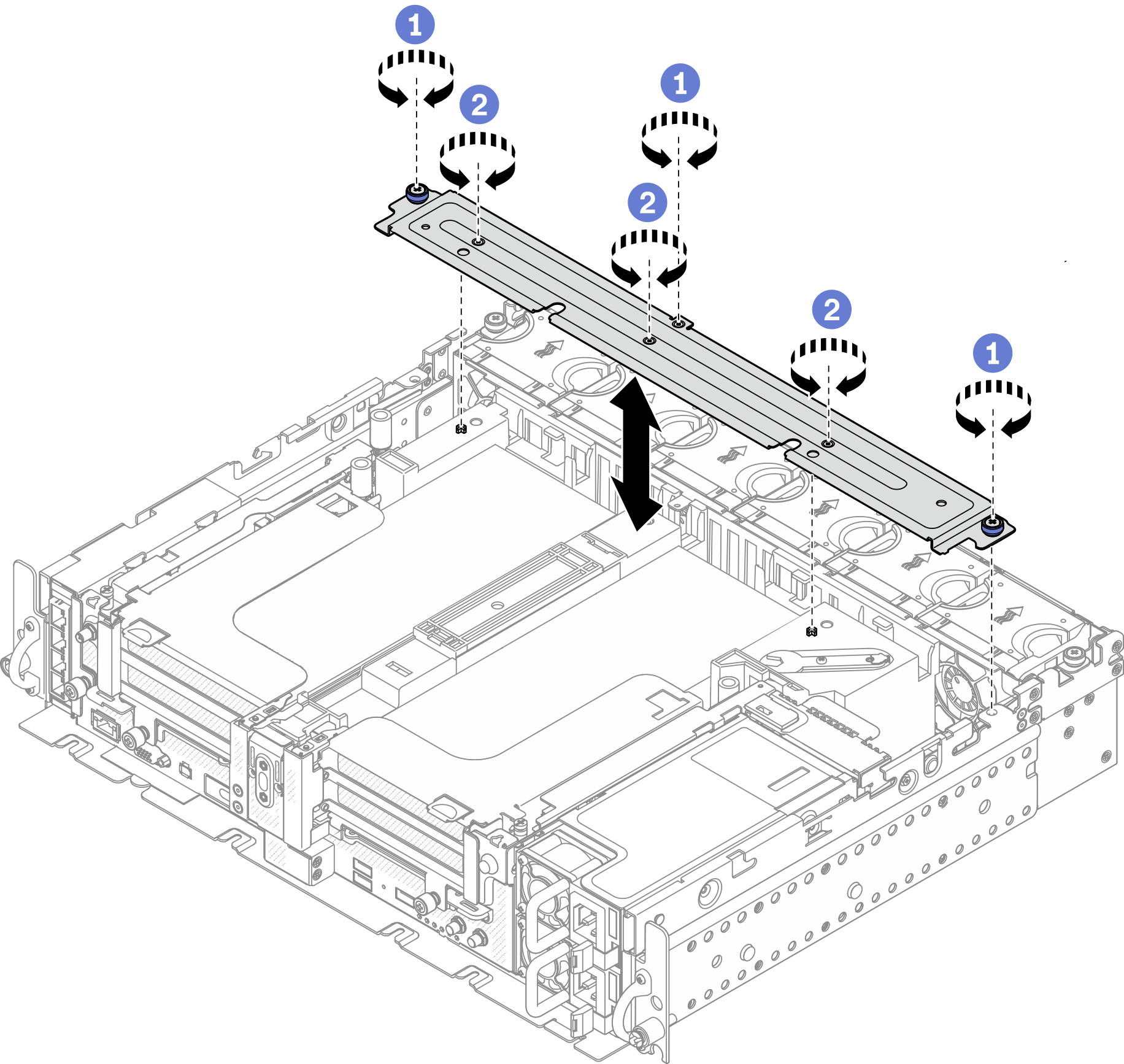
 Loosen the one captive screw and two thumbscrews that secure the bracket to the chassis.
 Loosen the other three screws, and remove the bracket from the air baffle.
- Disconnect the GPU power cables from the adapters.NoteIf there is a plan of replacing GPU power cables, make sure to remove the fan cage first (see
Remove the fans and the fan cage). Figure 8. Cable routing for GPU power cables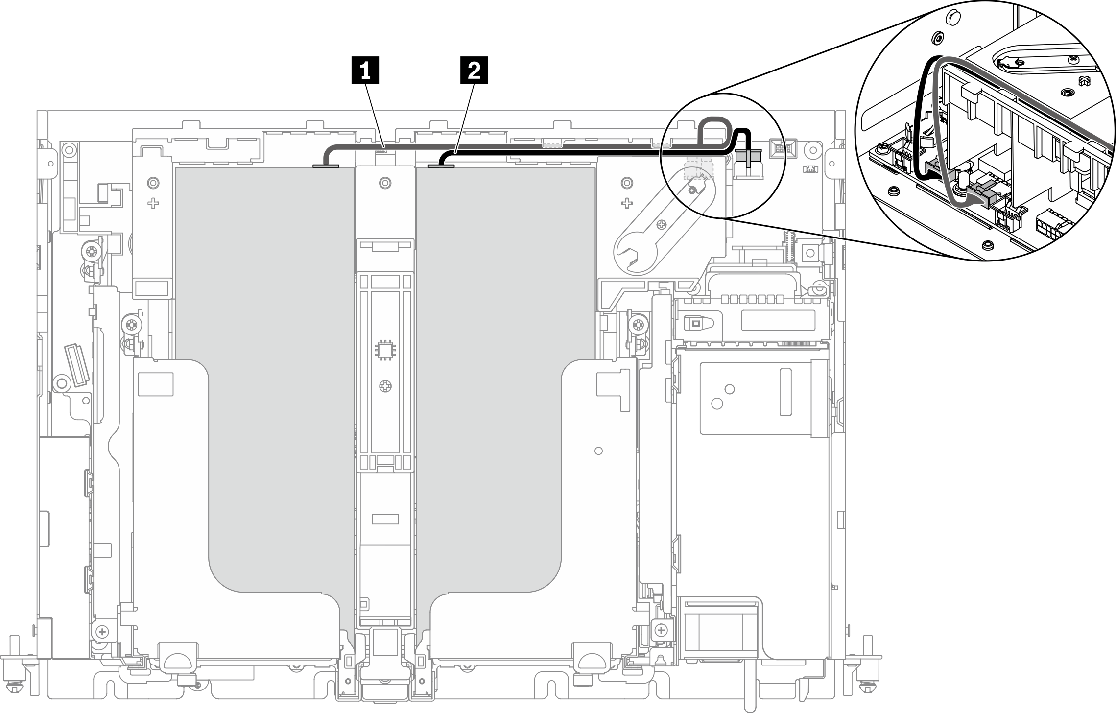
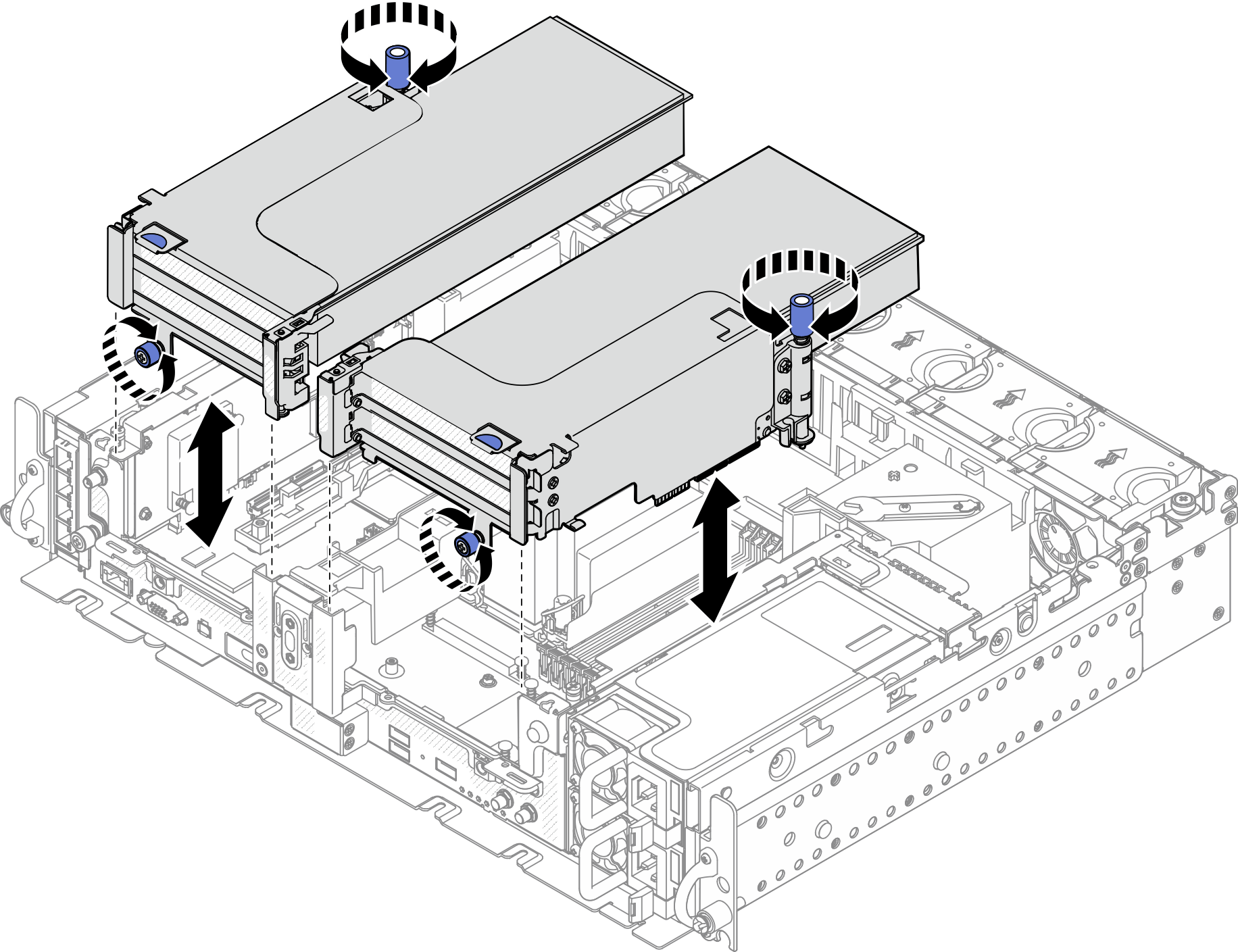
Table 1. Cable routing for GPU power cables From To 1 GPU in Slot 5, Riser 1 GPU power connector 2 2 GPU in Slot 4, Riser 2 GPU power connector 1 - Loosen the four captive screws; then lift and remove both PCIe riser assemblies.Figure 9. Removing PCIe riser assemblies with full-length adapters
- Open the retainer, and remove the screws that secure the adapter to the riser.Figure 10. Removing the retaining screws
- Press on the latch to disengage the adapter from the riser, and remove the adapter.Figure 11. Removing an adapter from the riser
- If necessary, lift the air baffle and remove it from the chassis.Figure 12. Removing the 360mm air baffle (with full-length adapters)
After this task is completed
If you are instructed to return the component or optional device, follow all packaging instructions, and use any packaging materials for shipping that are supplied to you.
- If there is a recycle plan, complete the following step corresponding to the component to be recycled:
- Remove the PCIe riser-card from the riser:
Riser 1
Remove the three screws that secure the riser card to the riser.Figure 13. Disassembling Riser 1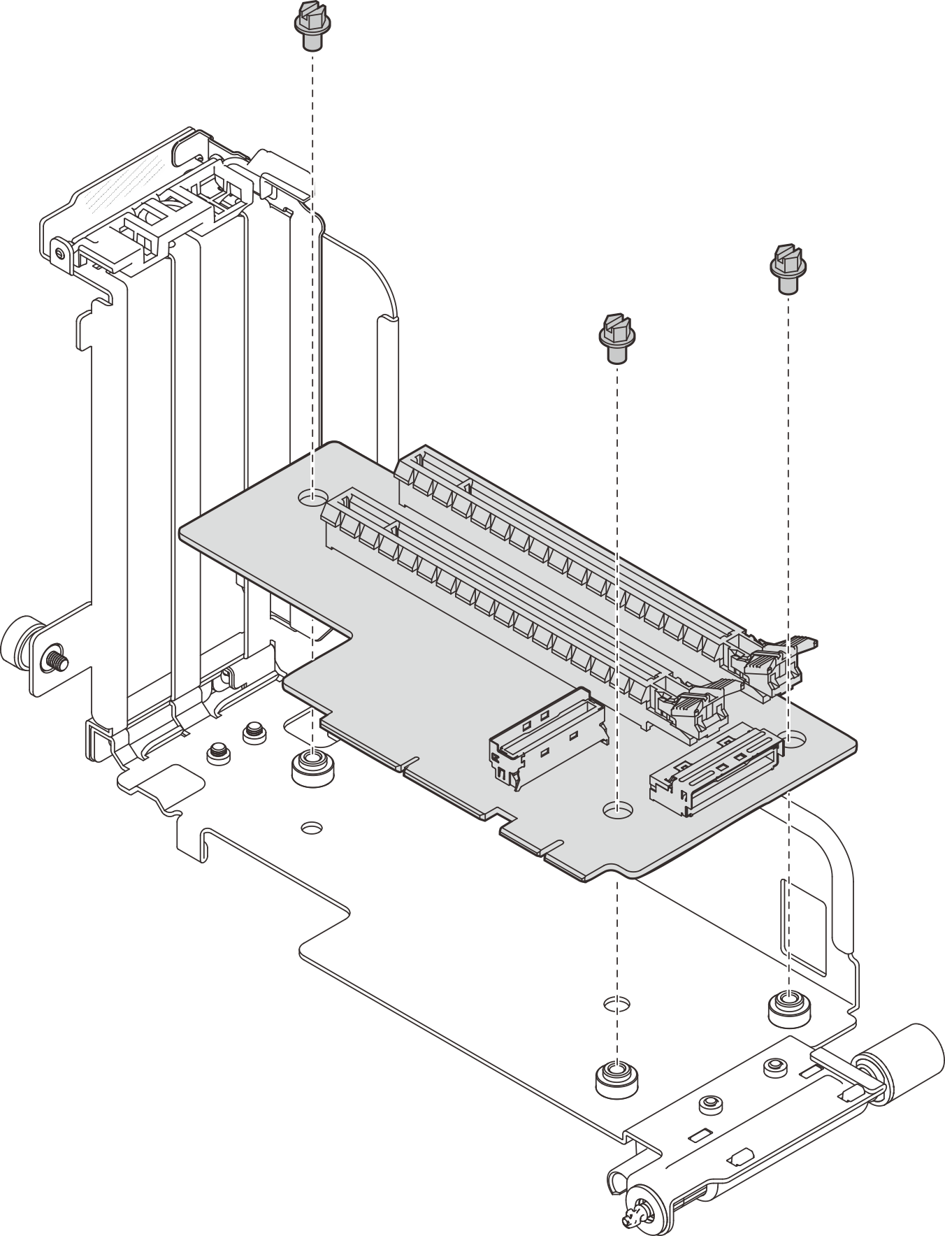
Riser 2
Remove the four screws that secure the riser card to the riser.Figure 14. Disassembling Riser 2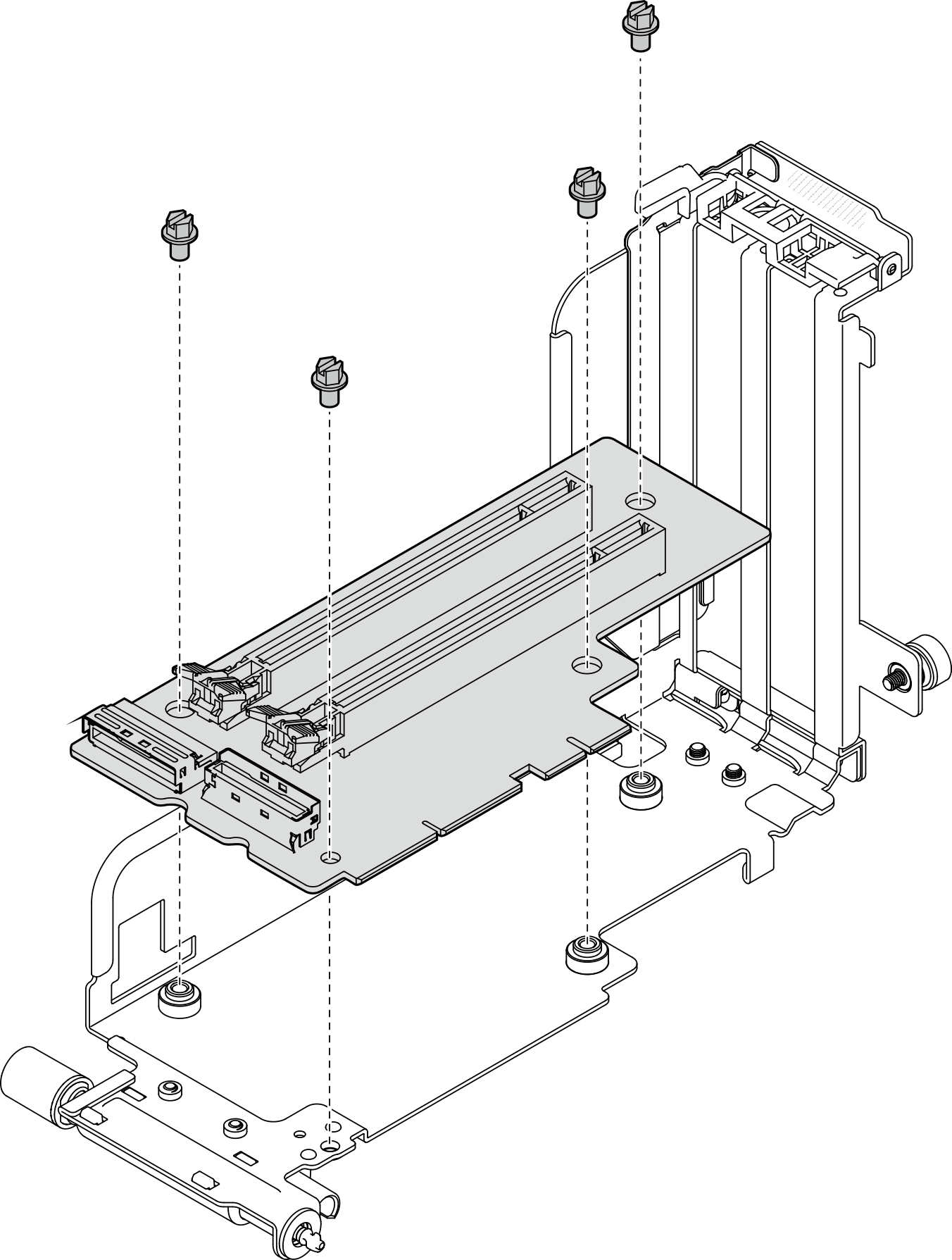
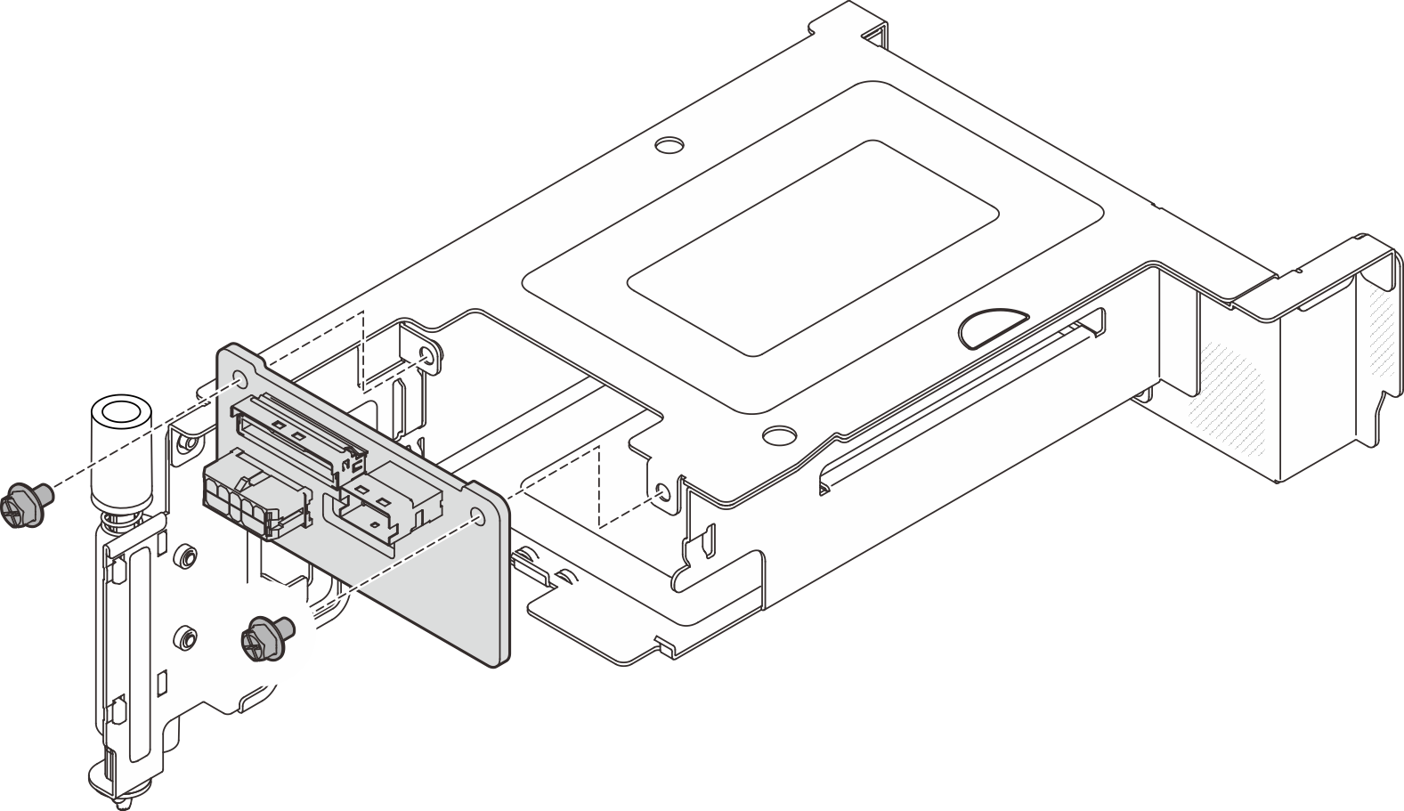
- Remove the AnyBay drive backplane from PCIe riser 2 with AnyBay drive cageRemove the two screws that secure the AnyBay drive backplane to the riser cage.Figure 15. Disassembling the AnyBay drive cage
- Remove the PCIe riser-card from the riser:
Give documentation feedback