System-board connectors
See this topic to identify the connectors on the system board.
Figure 1. System board connectors
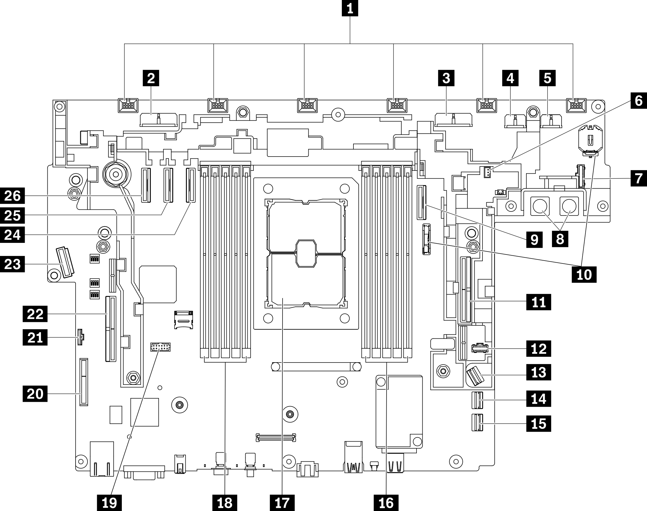
| 1 | Fan connectors (6 to 1) | 14 | SATA connector (0 to 3) |
| 2 | Drive power connector 2 | 15 | SATA connector (4 to 7) |
| 3 | Drive power connector 1 | 16 | DIMM slot 1 to 5 |
| 4 | GPU power connector 2 | 17 | Processor socket |
| 5 | GPU power connector 1 | 18 | DIMM slot 6 to 10 |
| 6 | Intrusion switch connector | 19 | Serial port module connector |
| 7 | Power backplane side band connector | 20 | (Reserved) |
| 8 | Power backplane power connector | 21 | Top cover/Wall-mount LED cable connector |
| 9 | PCIe connector 2 | 22 | PCIe connector 6 (Riser 1) |
| 10 | CMOS battery (3V, CR3032) slots | 23 | OCP 3.0 Ethernet adapter connector |
| 11 | PCIe connector 1 (Riser 2) | 24 | PCIe connector 3 |
| 12 | M.2 power connector | 25 | PCIe connector 4 |
| 13 | M.2 signal connector | 26 | PCIe connector 5 |
Give documentation feedback