Front view
See this topic to learn about the controls, LEDs, and connectors on the front of the server.
Front view
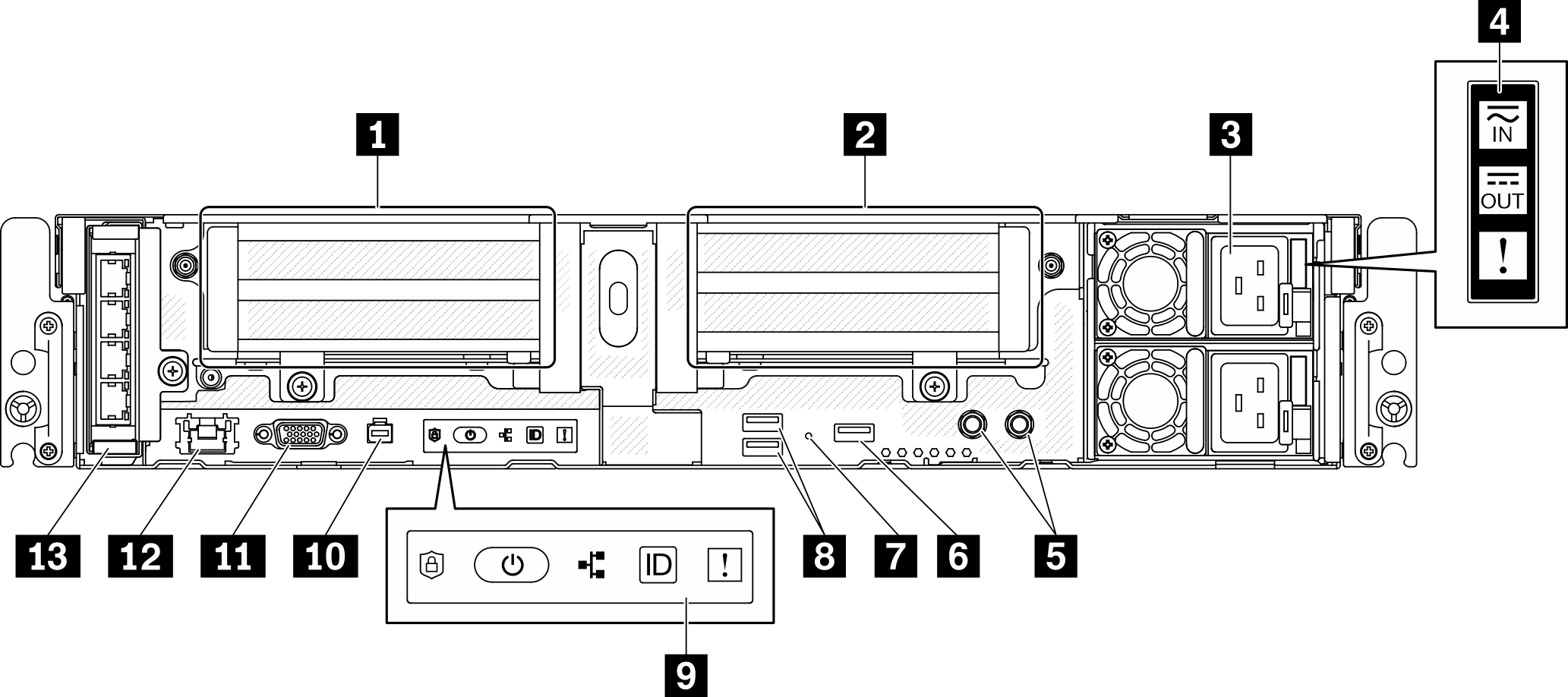
| 1 | Riser 1 (PCIe slot 5 and 6) | 8 | USB 3.0 connectors (1 and 2) |
| 2 | Riser 2 (PCIe Slot 3 and 4 / Hot-swap Drive 4 and 5) | 9 | Front operator panel |
| 3 | Power supply units (Bay 2 and 1) | 10 | External diagnostic handset connector |
| 4 | Power supply LEDs | 11 | VGA connector |
| 5 | Threaded studs for grounding | 12 | XClarity Controller (XCC) network connector |
| 6 | USB 2.0 with Lenovo XClarity Controller management | 13 | OCP 3.0 adapter (PCIe Slot 7) |
| 7 | NMI button |
1 Riser 1 (PCIe slot 5 and 6)
Supports the following:
Single-width PCI Express 4.0 x16/x8 (Slot 5, 6)
Single-width PCI Express 4.0 x16/x16 (Slot 5, 6)
Single/double-width PCI Express 4.0 x16 (Slot 5)
NoteRAID adapter must be installed in Slot 6.
2 Riser 2 (PCIe Slot 3 and 4 / Hot-swap Drive 4 and 5)
Supports the following:
Single-width PCI Express 4.0 x8/x16 (Slot 3, 4)
Single-width PCI Express 4.0 x16/x16 (Slot 3, 4)
Single/double-width PCI Express 4.0 x16 (Slot 4)
Two 2.5-inch hot-swap SAS/SATA/NVMe drives (Drive 4, 5)
3 Power supply units (bay 2 and 1)
- 1100-watt Platinum, input power 100-240 Vac
- 1100-watt Titanium, input power 100-240 Vac
- 1800-watt Platinum, input power 200-240 Vac
- 1100-watt -48V dc
4 Power supply LEDs
Power input LED (green)
Off: The power supply is disconnected from the ac power source or a power problem occurs.
Green: The power supply is connected to the ac power source.
Power output LED (green)
Green: The server is on and the power supply is working normally.
Blinking green: The power supply is in zero-output mode (standby). When the server power load is low, one of the installed power supplies enters into the standby state while the other one delivers entire load. When the power load increases, the standby power supply will switch to active state to provide sufficient power to the server.
To disable zero-output mode, start the Setup utility, go to System Settings > Power > Zero Output and select Disable. If you disable zero-output mode, both power supplies will be in the active state.
Off: The server is powered off, or the power supply is not working properly. If the server is powered on but the power output LED is off, replace the power supply.
Power supply error LED (yellow)
Off: The power supply is working.
Yellow: The power supply has failed. To resolve the issue, replace the power supply.
5 Threaded studs for grounding
Connect the grounding wires to these lugs.
6 USB 2.0 with Lenovo XClarity Controller management
Connection to XClarity Controller is primarily intended for users with a mobile device running the XClarity Controller mobile application. When a mobile device is connected to this USB port, an Ethernet over USB connection is established between the mobile application running on the device and the XClarity Controller. Select Network in BMC Configuration to view or modify settings.
BMC only mode
In this mode, the USB port is always solely connected to XClarity Controller.
7 NMI button
Press this button to force a nonmaskable interrupt to the processor. You might have to use a pen or the end of a straightened paper clip to press the button. You can also use it to force a blue-screen memory dump. Use this button only when you are directed to do so by Lenovo Support.
8 USB 3.0 connectors (1 and 2)
Connect a USB device, such as a mouse, keyboard, or other devices, to either of these connectors.
9 Front operator panel
See Front operator panel for details.
10 External diagnostic handset connector
Connect the External diagnostic handset to this connector for system diagnostics and trouble shooting. See External LCD diagnostics handset for details.
11 VGA connector
Connect a monitor to this connector. The maximum video resolution is 1920 x 1200 at 60 Hz.
12 XClarity Controller (XCC) network connector
Use this connector to manage the server, by using a dedicated management network. If you use this connector, the Lenovo XClarity Controller cannot be accessed directly from the production network. A dedicated management network provides additional security by physically separating the management network traffic from the production network. You can use the Setup utility to configure the server to use a dedicated systems-management network or a shared network.
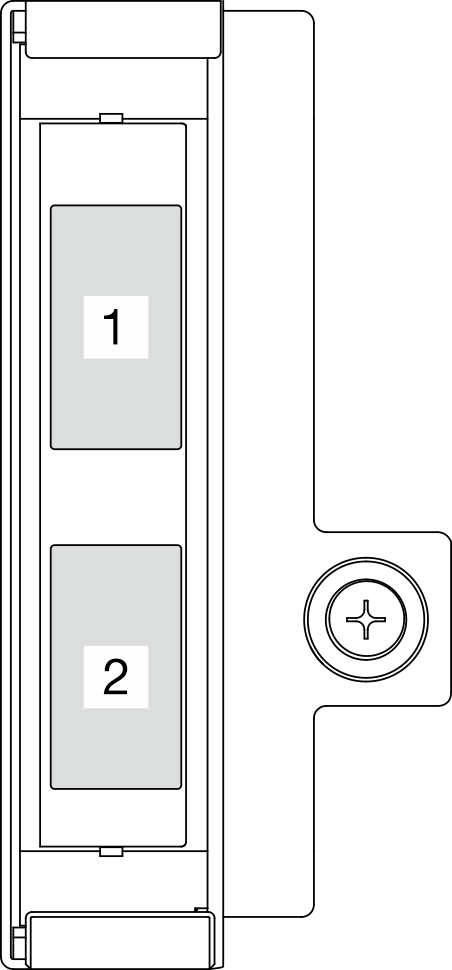
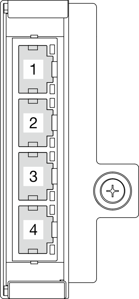
13 OCP 3.0 adapter (Slot 7)
The OCP 3.0 Ethernet adapter provides two or four extra Ethernet connectors for network connections. See the following for port numbering:
Figure 2. Port numbering: 2-port OCP 3.0 adapter
| Figure 3. Port numbering: 4-port OCP 3.0 adapter
|
One of the Ethernet connectors on the OCP 3.0 Ethernet adapter can also function as a management connector with shared management capacity. If the shared management connector fails, traffic can automatically switch over to another connector on the adapter.
I/O fillers
Install the I/O fillers when the connectors are not used. The connectors could be damaged without proper protection of the fillers.
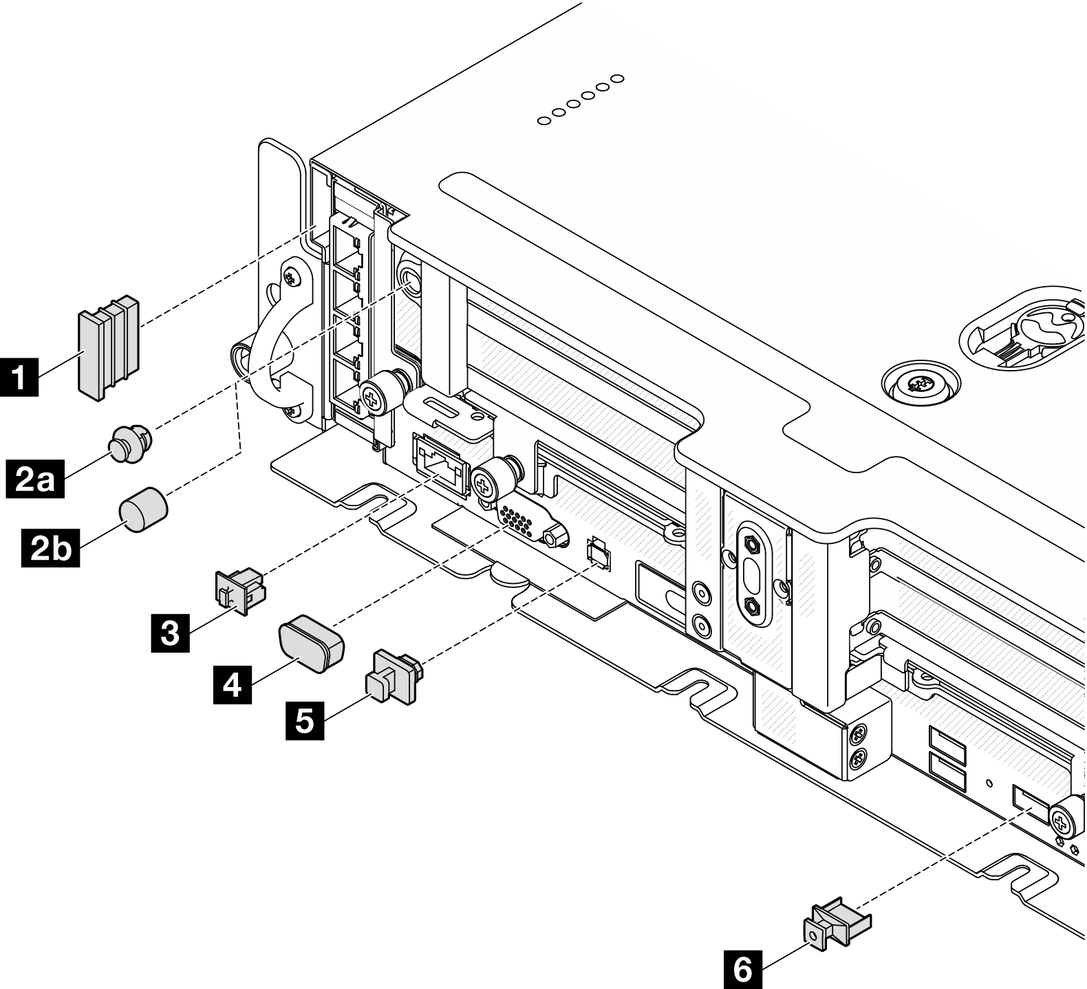
| 1 Security bezel filler (x2) | 4 VGA cover (x1) |
2a Antenna port filler (x2) or 2b antenna cover (x2)* | 5 External diagnostic handset connector filler (x1) |
| 3 RJ-45 filler (x1) | 6 USB Type-A filler (x3) |
*Depending on the configuration, install the antenna port fillers or the antenna covers on the front of the server. ThinkEdge SE450 uses the antenna port fillers only.