Remove the adapter-retention assembly

Use this information to remove the adapter-retention assembly.

About this task
Attention
  1. Read Safety inspection checklist and Installation Guidelines to ensure that you work safely.

  2. Power off the corresponding compute node that you are going to perform the task on.

  3. Remove the compute node from the chassis. See Remove the compute node from chassis.

  4. Carefully lay the compute node on a flat, static-protective surface, orienting the compute node with the bezel pointing toward you.

  5. Make sure you have a T10 Torx screwdriver available.

Note

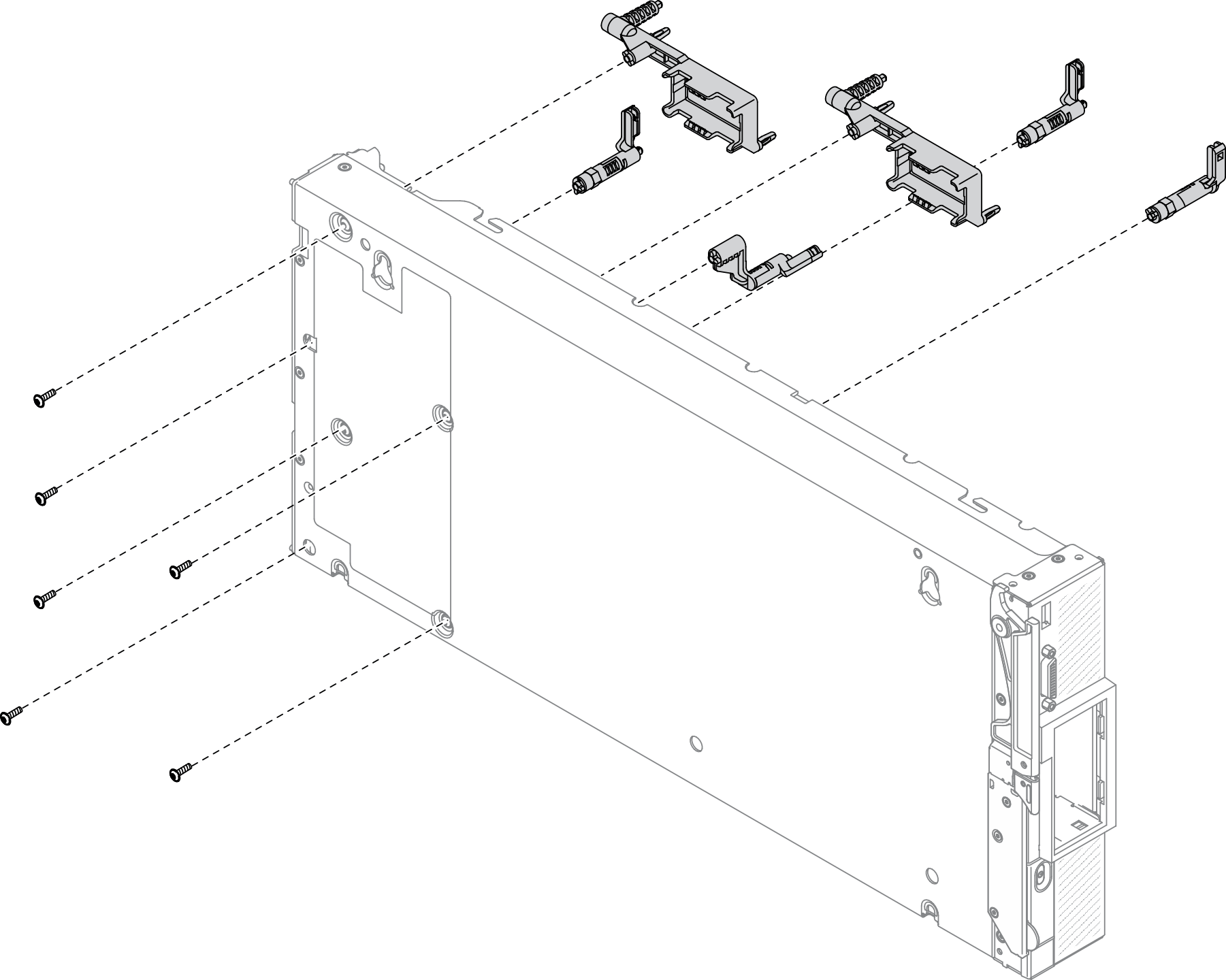
The adapter-retention assembly consists of 12 separate parts. You can replace only the parts that you choose and save the unused parts for future use.

Procedure

  1. Make preparations for your compute node.
    1. Remove the compute node cover. See Remove the compute node cover.
    2. Remove the air baffle. See Remove the air baffle.
    3. If present, remove the I/O expansion adapters from the system board. See Remove an I/O expansion adapter.
    4. If present, disconnect M.2 cables from the system board. See Step 2 in Remove the M.2 backplane assembly.
      Attention
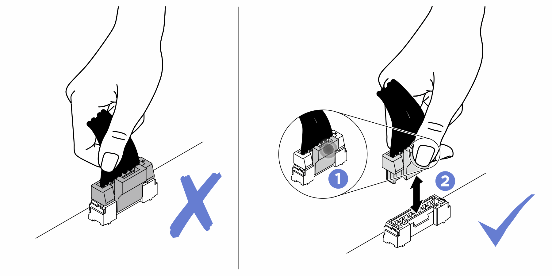
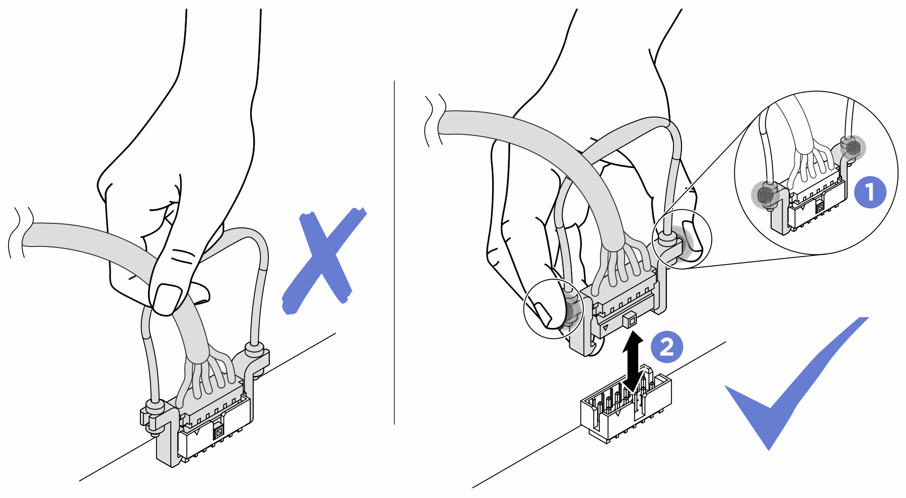
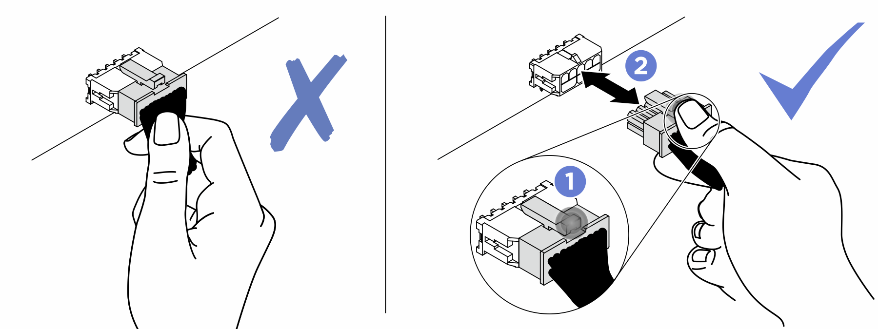
      Strictly observe the following instructions to avoid damaging cable sockets on the system board. Any damage to the cable sockets might require replacing the system board.
      • Connect cable connectors vertically or horizontally in alignment with the orientations of the corresponding cable sockets, avoiding any tilt.

      • To disconnect cables from the system board, do as follows:
        1. Press and hold all latches, release tabs, or locks on cable connectors to release the cable connectors.

        2. Remove the cable connectors vertically or horizontally in alignment with the orientations of the corresponding cable sockets, avoiding any tilt.
          Note
          The cable connectors might look different from those in the illustration, but the removal procedure is the same.


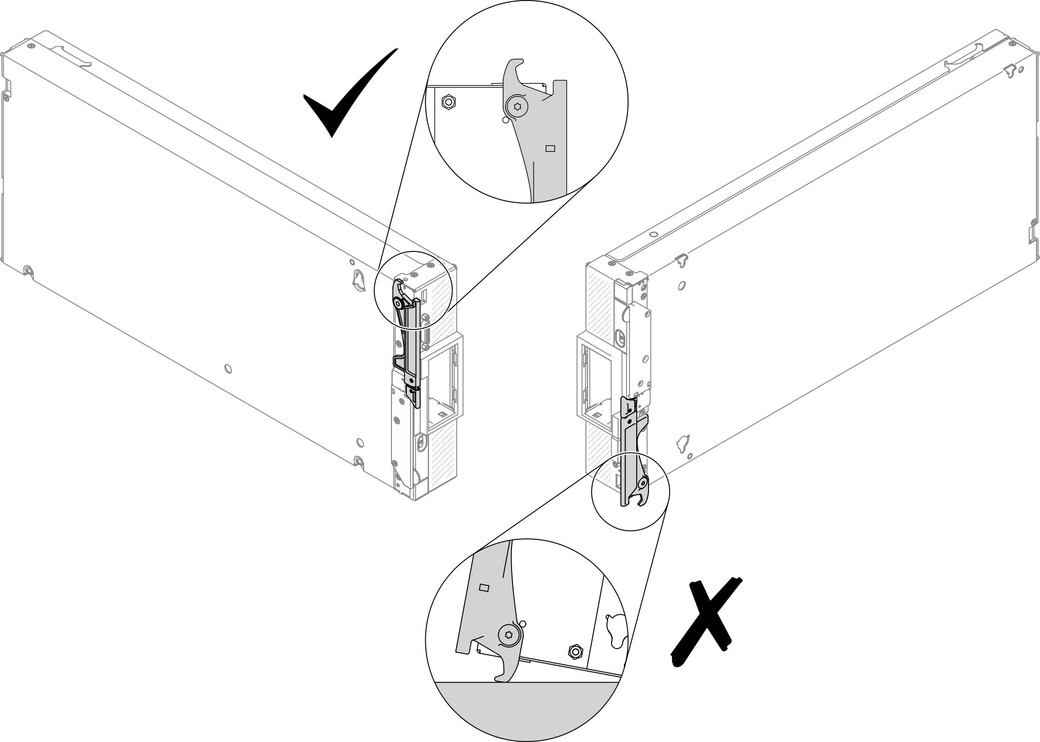
  2. Carefully place the compute node on its side, making sure the protruding part of the handle is at the top so that the compute node is stable.
    Attention
    If you place the compute node on its side, with the protruding part of the handle at the bottom, the compute node will not be stable and might fall over.
    Figure 1. Compute node positioning direction
    Compute node positioning direction
  3. Using a T10 Torx screwdriver, remove the screws that secure the adapter-retention assembly. Remove the adapter-retention assembly away from the system board.
    Note
    All adapter-attention assembly parts are shown. Replace the parts that are needed and save the unused parts for future use.
    Figure 2. Adapter-retention assembly removal
    Adapter-retention assembly removal
  4. Carefully return the compute node to the bottom-side-down orientation.

After you finish

If you are instructed to return the component or optional device, follow all packaging instructions, and use any packaging materials for shipping that are supplied to you.