System-board switches
Use this information to locate the system-board switches.
Note
If there is a clear protective sticker on the top of the switch blocks, you must remove and discard it to access the switches.
The following illustration shows the location of the switch blocks on the system board.
Figure 1. Switch blocks
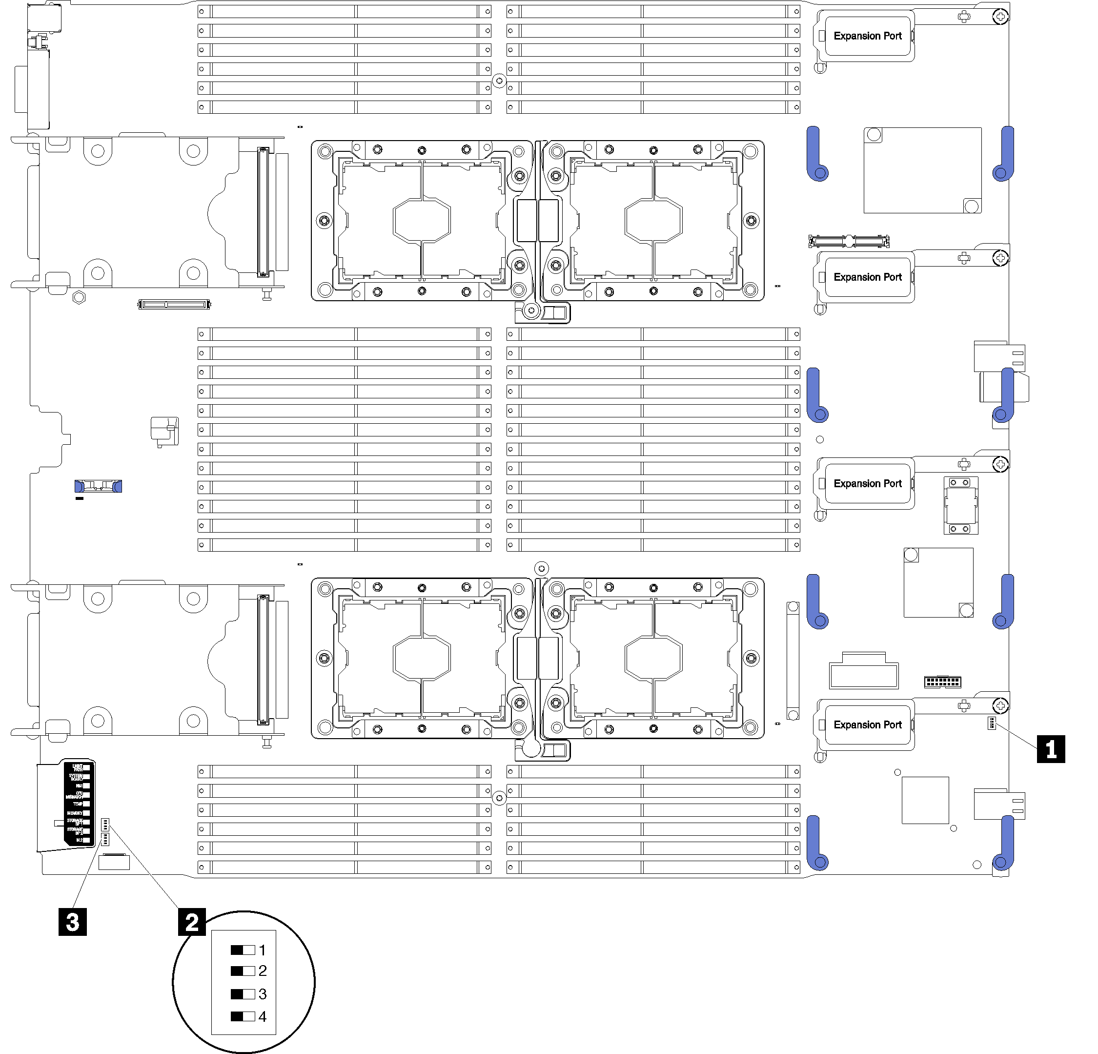
| 1 SW1 switch block | 3 SW2 switch block |
| 2 SW5 switch block |
Important
Any system-board switches or jumpers that are not described in this section are reserved.
- Before you change any switch settings or move any jumpers, power off the compute node. Review the information in Safety Information page, Installation Guidelines, Handling static-sensitive devices, and Power off the compute node.
Switch and jumper functions are as follows:
- All jumpers on the system board are reserved and should be removed.
- All switches should be in the Off position.
The following table describes the functions of the switches on switch block SW5.
Table 2. System-board switch block Switch number Description Definition SW5-1 Password override The default position is Off. Changing this switch to the On position overrides the power-on password. SW5-2 Trusted Platform Module (TPM) physical presence The default position is Off. Changing this switch to the On position indicates a physical presence to the TPM. SW5-3 CMOS memory The default position is Off. Changing this switch to the On position indicates to clear CMOS memory. After clearing the CMOS memory, change the switch back to Off position to turn on the compute node (see Power on the compute node for instructions).
SW5-4 Reserved The default position is Off.
Give documentation feedback