System-board-assembly switches
The following illustrations show the location of the switches on the server. Depending on the server model, the system board might be different from the following illustration, but the location and the block description of the switches are the same.
Note
If there is a clear protective sticker on the top of the switch blocks, you must remove and discard it to access the switches.
Important
Before you change any switch settings or move any jumpers, turn off the server; then, disconnect all power cords and external cables. Review the following information:
- Any system-board switch or jumper block that is not shown in the illustrations in this document are reserved.
Figure 1. System-board-assembly switches
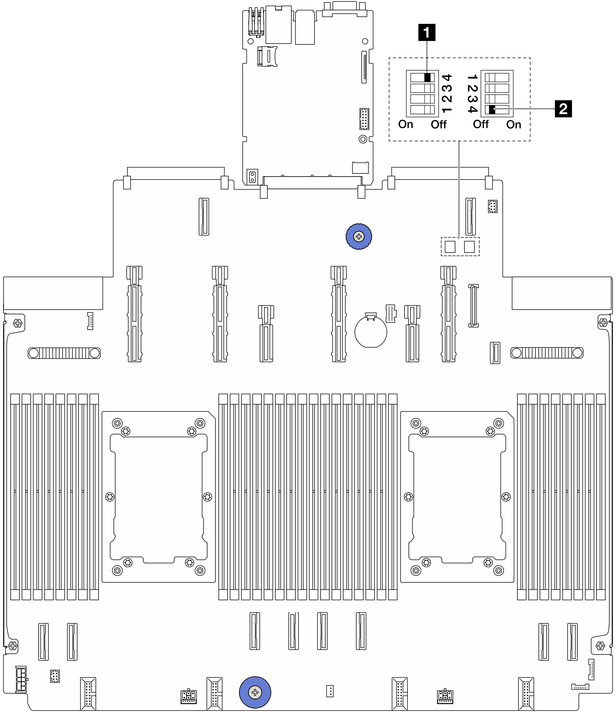
SW1 switch block
The following table describes the functions of the SW1 switch block on the system board assembly.
| Switch-bit number | Switch name | Default position | Description |
|---|---|---|---|
| 1 SW1–1 | Reserved | OFF | Reserved |
| 2 SW1–2 | Reserved | OFF | Reserved |
| 3 SW1–3 | Reserved | OFF | Reserved |
| 4 SW1–4 | Clear CMOS | OFF | Clears the real-time clock (RTC) registry when switched to ON. |
SW2 switch block
The following table describes the functions of the SW2 switch block on the system board assembly.
| Switch-bit number | Switch name | Default position | Description |
|---|---|---|---|
| 1 SW2–1 | Reserved | OFF | Reserved |
| 2 SW2–2 | Reserved | OFF | Reserved |
| 3 SW2–3 | Reserved | OFF | Reserved |
| 4 SW2–4 | Password bypass | OFF | Bypass the power-on password when switched to ON. |
Give documentation feedback