System-board-assembly connectors
The following illustrations show the internal connectors on the system board assembly.
Note
Depending on the model, 42 Second management Ethernet connector might not be available.
Servers without Compute Complex Neptune Core Module
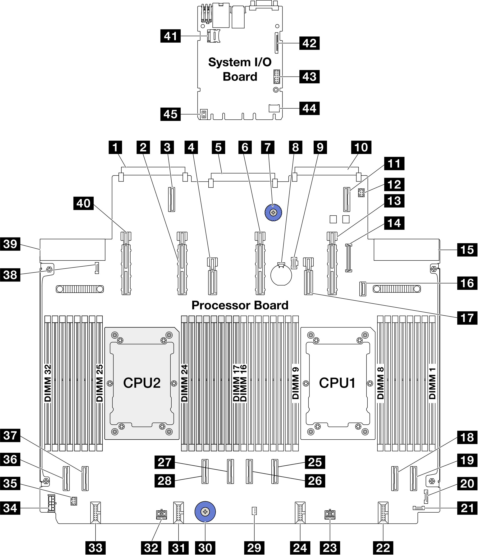
| 1 OCP 3.0 network card connector 2 | 2 Power & PCIe connector 13 |
| 3 OCP expansion connector 2 | 4 Power & PCIe connector 12 |
| 5 System I/O board connector | 6 Power & PCIe connector 11 |
| 7 Lift Handle | 8 3V battery (CR2032) |
| 9 M.2 power connector | 10 OCP 3.0 network card connector 1 |
| 11 OCP expansion connector 1 | 12 Pump 1 connector |
| 13 Power & PCIe connector 9 | 14 Front panel USB connector |
| 15 Power supply 1 connector | 16 M.2 BP signal connector |
| 17 Power & PCIe connector 10 | 18 PCIe connector 2 |
| 19 PCIe connector 1 | 20 FIO connector |
| 21 Leak detection connector 1 | 22 Fan 1-2 connector |
| 23 Power connector 3A | 24 Fan 3-4 connector |
| 25 PCIe connector 3 | 26 PCIe connector 4 |
| 27 PCIe connector 5 | 28 PCIe connector 6 |
| 29 Intrusion switch connector | 30 Lift handle |
| 31 Fan 5-6 connector | 32 Power connector 2A |
| 33 Fan 7-8 connector | 34 Internal RAID power connector |
| 35 Pump 2 connector | 36 PCIe connector 8 |
| 37 PCIe connector 7 | 38 Leak detection connector 2 |
| 39 Power supply 2 connector | 40 Power & PCIe connector 15 |
| 41 MicroSD socket | 42 Second management Ethernet connector |
| 43 Serial port connector | 44 TCM connector |
| 45 Lift handle |
Servers with Compute Complex Neptune Core Module
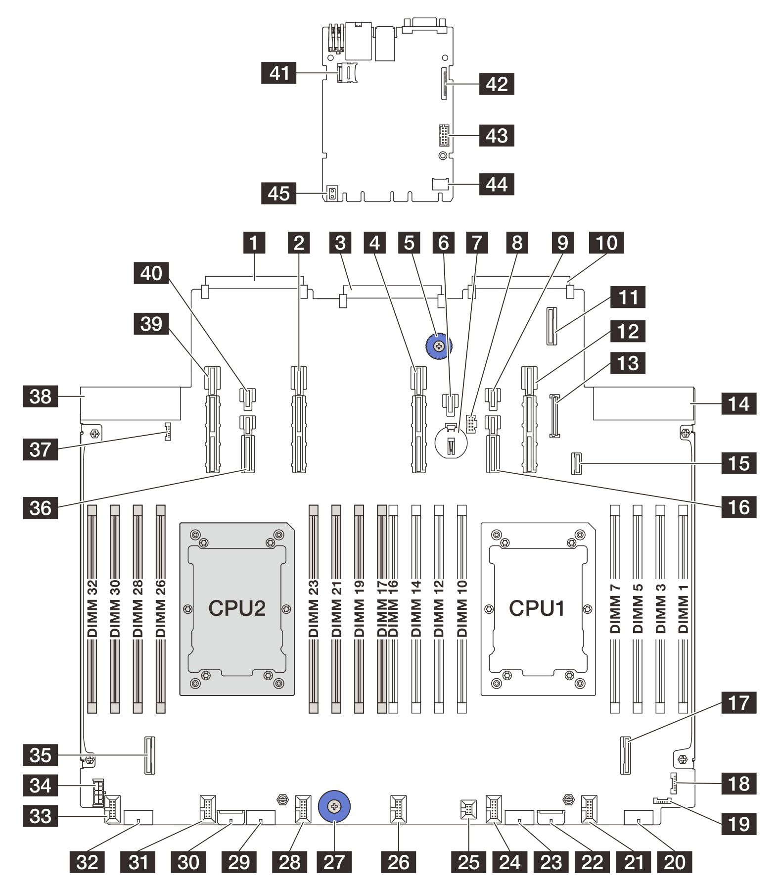
| 1 OCP 3.0 network card connector 2 | 2 Power & PCIe connector 13 |
| 3 System I/O board connector | 4 Power & PCIe connector 11 |
| 5 Lift Handle | 6 Power connector 21 |
| 7 3V battery (CR2032) | 8 M.2 power connector |
| 9 Power connector 20 | 10 OCP 3.0 network card connector 1 |
| 11 OCP expansion connector 1 | 12 Power & PCIe connector 9 |
| 13 Front panel USB connector | 14 Power supply 1 connector |
| 15 M.2 BP signal connector | 16 Power & PCIe connector 10 |
| 17 PCIe connector 2 | 18 FIO connector |
| 19 Leak detection connector 1 | 20 Power connector 4 |
| 21 Fan 1 connector | 22 Expander power connector |
| 23 Power connector 3 | 24 Fan 2 connector |
| 25 Intrusion switch connector | 26 Fan 3 connector |
| 27 Lift handle | 28 Fan 4 connector |
| 29 Power connector 2 | 30 RAID power connector (SR650 V4) |
| 31 Fan 5 connector | 32 Power connector 1 |
| 33 Fan 6 connector | 34 RAID power connector (SR630 V4) |
| 35 PCIe connector 7 | 36 Power & PCIe connector 14 |
| 37 Leak detection connector 2 | 38 Power supply 2 connector |
| 39 Power & PCIe connector 15 | 40 Power connector 23 |
| 41 MicroSD socket | 42 Second management Ethernet connector |
| 43 Serial port connector | 44 TCM connector |
| 45 Lift handle |
Give documentation feedback