Front view
Front views vary by models. Depending on the model, the server might look slightly different from the illustrations in this topic.
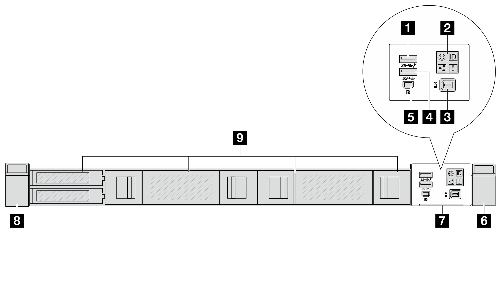
Front view of 4 x 2.5-inch drive configuration
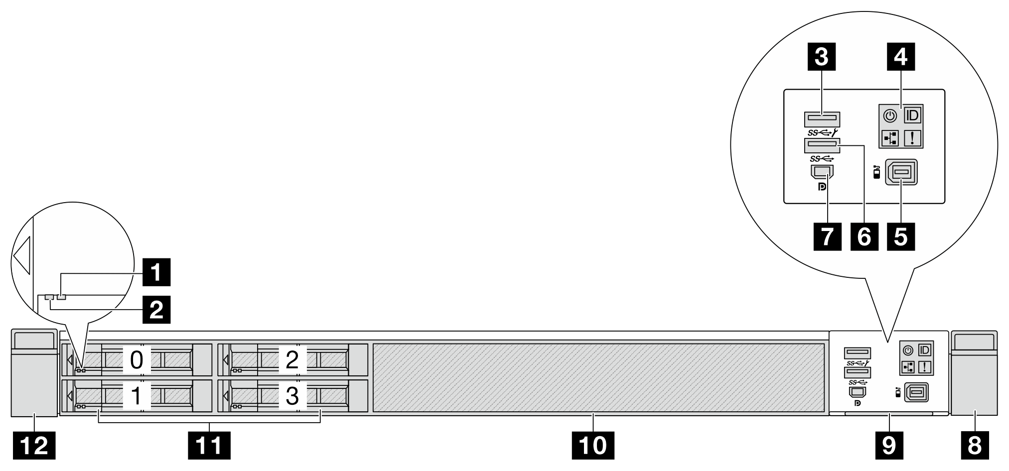
| 1 Drive status LED | 2 Drive activity LED |
3 USB 3.2 Gen 1(5Gbps) connector with USB 2.0 XCC system management (Optional) Note | 4 Diagnostics panel |
| 5 External LCD connector | 6 USB 3.2 Gen 1 (5Gbps) connector (Optional) |
| 7 Mini DisplayPort connector | 8 Rack latch (right) |
| 9 Pull-out information tab | 10 Drive bay filler (1) |
| 11 Drive bays (4) | 12 Rack latch (left) |
Front view of 4 x 2.5-inch drive and 2 x M.2 drive configuration
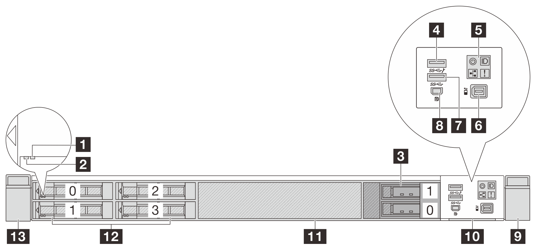
| 1 Drive status LED | 2 Drive activity LED |
| 3 M.2 drive bays | 4 USB 3.2 Gen 1(5Gbps) connector with USB 2.0 XCC system management (Optional) Note |
| 5 Diagnostics panel | 6 External LCD connector |
| 7 USB 3.2 Gen 1 (5Gbps) connector (Optional) | 8 Mini DisplayPort connector |
| 9 Rack latch (right) | 10 Pull-out information tab |
| 11 Drive bay filler (1) | 12 Drive bays (4) |
| 13 Rack latch (left) |
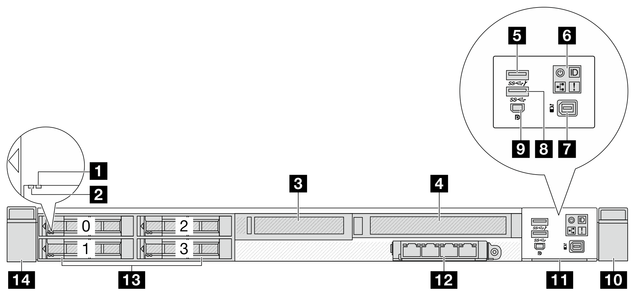
Front view of 4 x 2.5-inch drive bays and a front adapter assembly
| Callout | Callout |
|---|---|
| 1 Drive status LED | 2 Drive activity LED |
| 3 Front low-profile adapter assembly (Slot 4) | 4 Front full-height adapter assembly (Slot 5) |
| 5 USB 3.2 Gen 1(5Gbps) connector with USB 2.0 XCC system management (Optional)Note | 6 Diagnostics panel |
| 7 External LCD connector | 8 USB 3.2 Gen 1 (5Gbps) connector (Optional) |
| 9 Mini DisplayPort connector | 10 Rack latch (right) |
| 11 Pull-out information tab | 12 Front OCP module (Slot 8) |
| 13 Drive bays (4) | 14 Rack latch (left) |
For more information about each component, see Front components overview.
For the PCIe adapters supported in the servers installed with 4 x 2.5-inch drive bays and front adapter assembly, contac Lenovo Sales.
Front view of 8 x 2.5-inch drive configuration
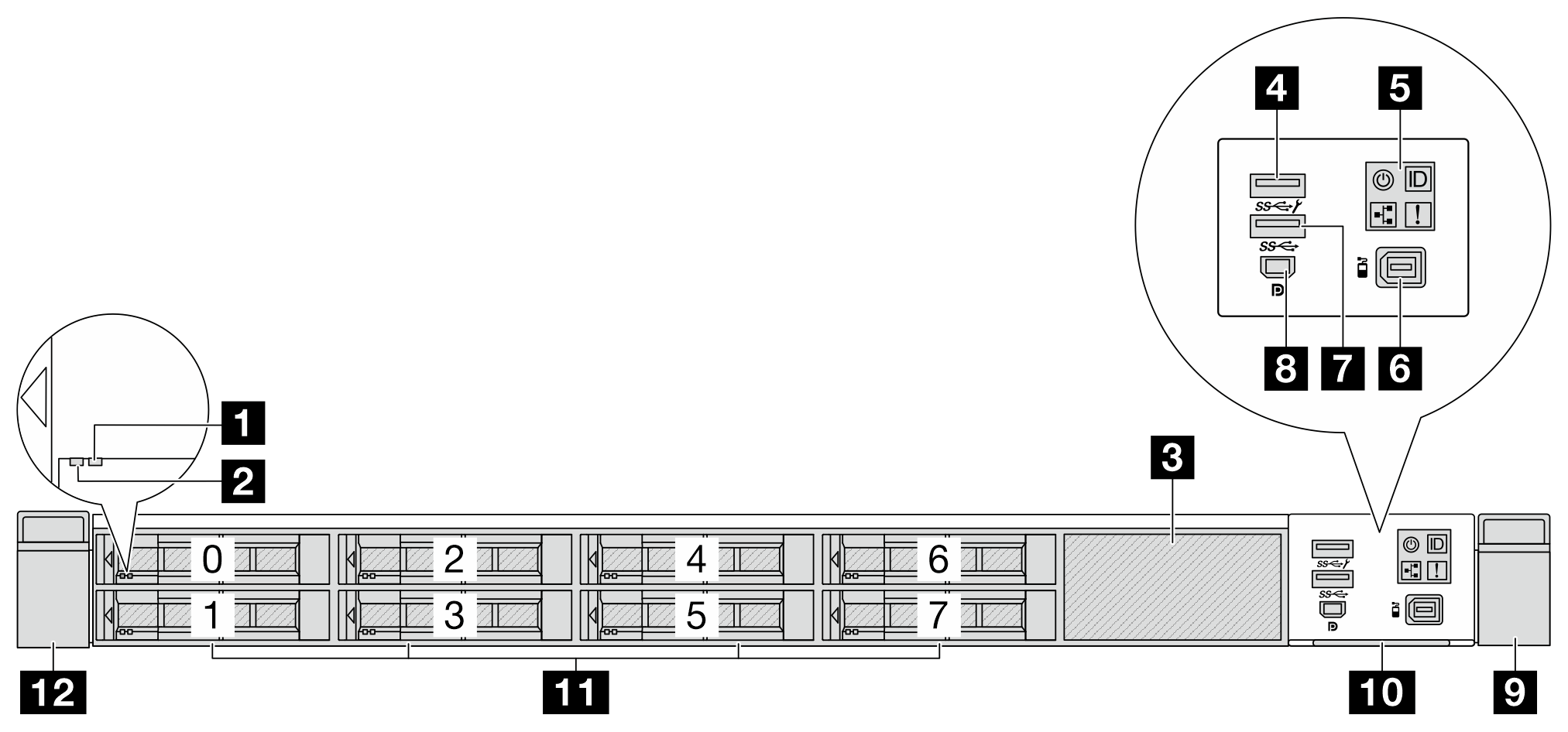
| 1 Drive status LED | 2 Drive activity LED |
| 3 Drive filler (1) | 4 USB 3.2 Gen 1(5Gbps) connector with USB 2.0 XCC system management (Optional)Note |
| 5 Diagnostics panel | 6 External LCD connector |
| 7 USB 3.2 Gen 1 (5Gbps) connector (Optional) | 8 Mini DisplayPort connector |
| 9 Rack latch (right) | 10 Pull-out information tab |
| 11 Drive bays (8) | 12 Rack latch (left) |
Front view of 8 x 2.5-inch and 2 x M.2 drive configuration
| 1 Drive status LED | 2 Drive activity LED |
| 3 M.2 drive bays | 4 USB 3.2 Gen 1(5Gbps) connector with USB 2.0 XCC system management (Optional)Note |
| 5 Diagnostics panel | 6 External LCD connector |
| 7 USB 3.2 Gen 1 (5Gbps) connector (Optional) | 8 Mini DisplayPort connector |
| 9 Rack latch (right) | 10 Pull-out information tab |
| 11 Drive bays (8) | 12 Rack latch (left) |
Front view of 10 x 2.5-inch drive configuration
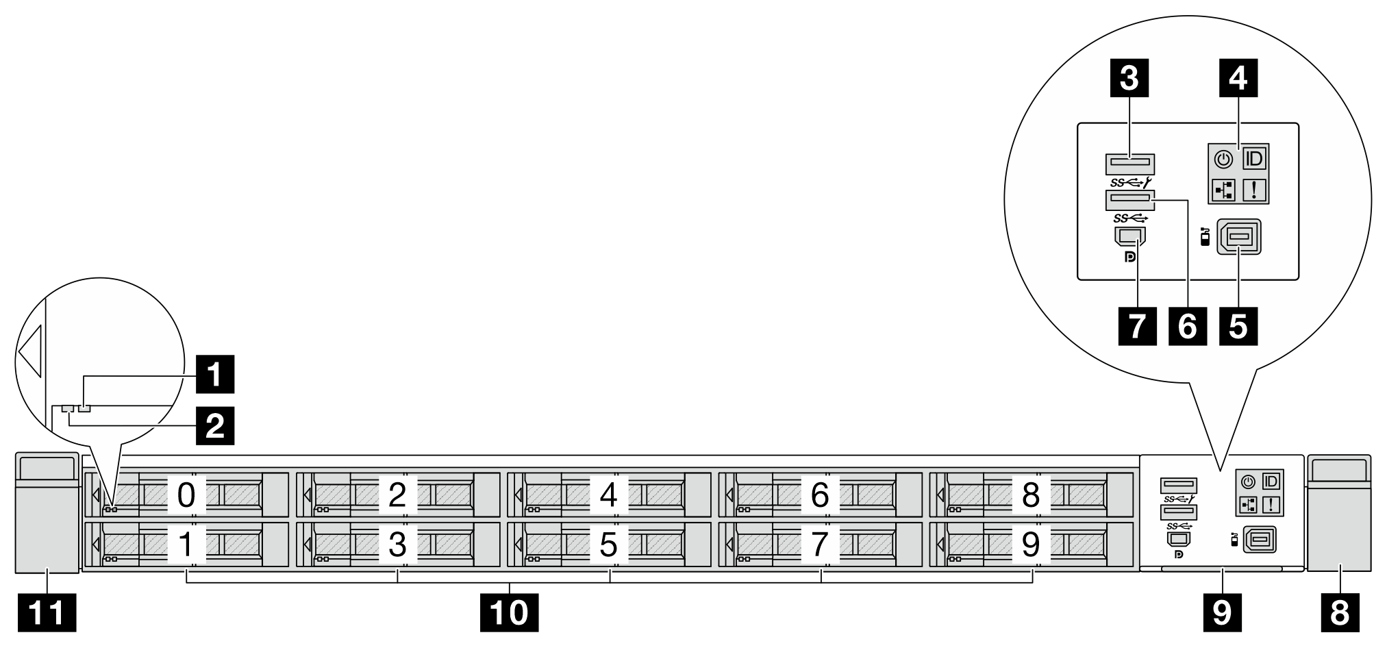
| 1 Drive status LED | 2 Drive activity LED |
3 USB 3.2 Gen 1(5Gbps) connector with USB 2.0 XCC system management (Optional) Note | 4 Diagnostics panel |
| 5 External LCD connector | 6 USB 3.2 Gen 1 (5Gbps) connector (Optional) |
| 7 Mini DisplayPort connector | 8 Rack latch (right) |
| 9 Pull-out information tab | 10 Drive bays (10) |
| 11 Rack latch (left) |
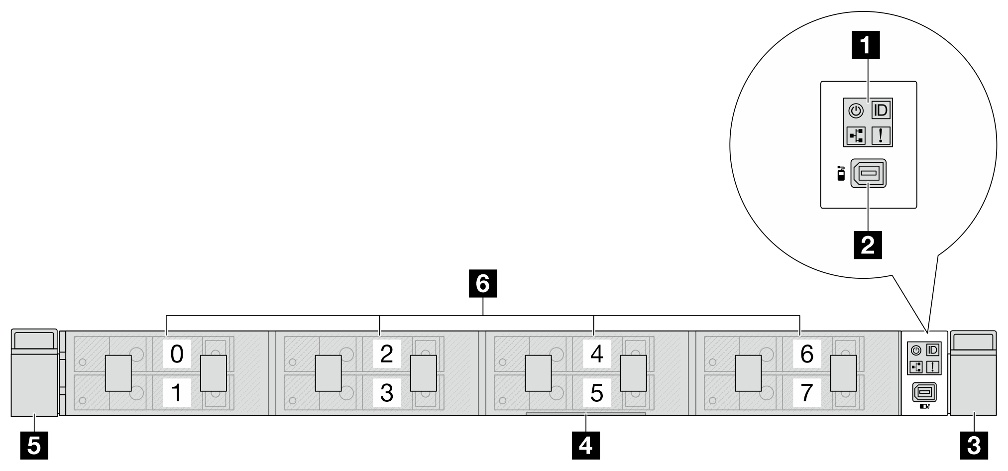
Front view of 1T E3.S drive configuration
| 1 Diagnostics panel | 2 External LCD connector |
| 3 Rack latch (right) | 4 Pull-out information tab |
| 5 Rack latch (left) | 6 Drive bays |
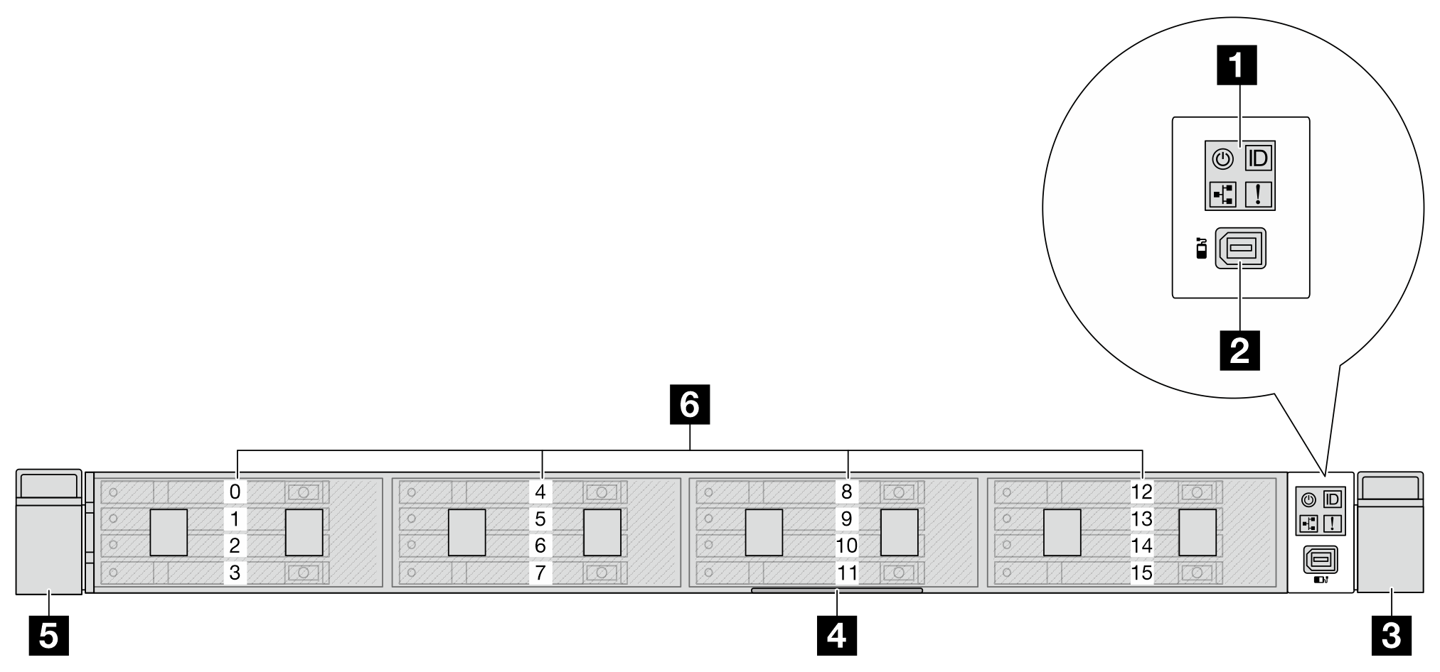
Front view of 2T E3.S drive configuration
| 1 Diagnostics panel | 2 External LCD connector |
| 3 Rack latch (right) | 4 Pull-out information tab |
| 5 Rack latch (left) | 6 Drive bays |
Front view of 1T/2T E3.S and M.2 drive configuration
| 1 Diagnostics panel | 2 External LCD connector |
| 3 Rack latch (right) | 4 M.2 drive bays |
| 5 Pull-out information tab | 6 Rack latch (left) |
| 7 Drive bays |
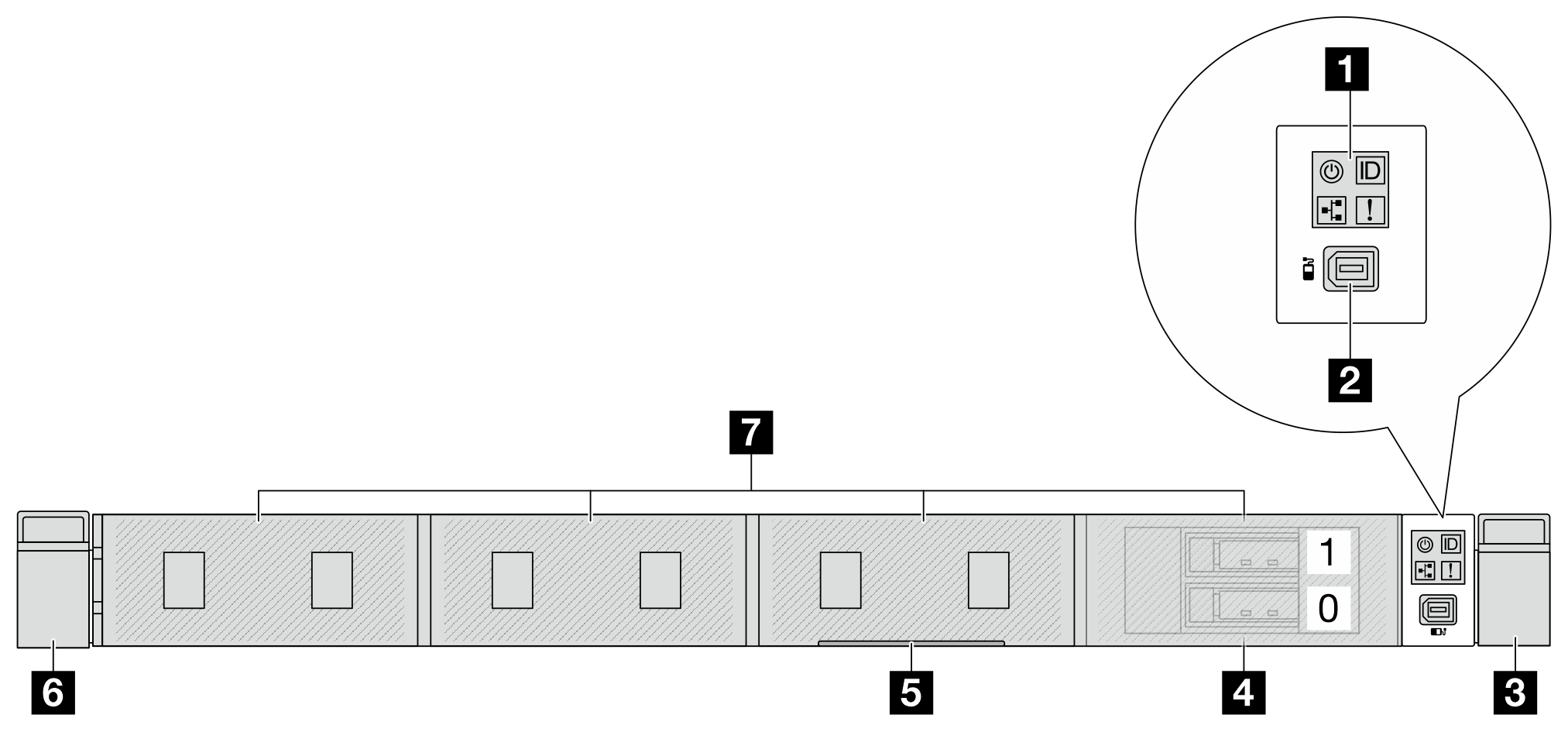
Front view of no backplane configuration
3 USB 3.2 Gen 1(5Gbps) connector with USB 2.0 XCC system management (Optional) Note | 2 Diagnostics panel |
| 3 External LCD connector | 4 USB 3.2 Gen 1 (5Gbps) connector (Optional) |
| 5 Mini DisplayPort connector | 6 Rack latch (right) |
| 7 Pull-out information tab | 8 Rack latch (left) |
| 9 Drive fillers |
Front components overview
Front I/O module
Figure 1. FIO module with USB/MiniDP  | Figure 2. Standard FIO module  |
| The module supports two USB connectors, one MiniDP connector and a front operator panel. | The module supports a front operator panel. |
External diagnostics port
The connector is for connecting an external diagnostics handset. For more about its functions, see External diagnostics handset
in User Guide or Hardware Maintenance Guide.
Front operator panel
The assembly comes with an integrated LCD diagnostics panel that can be used to quickly obtain system status, firmware levels, network information, and health information about the system. For more about the panel functions, see Front operator panel.
Hot-swap drives and drive bays
The drive bays on the front and rear of your server are designed for hot-swap drives or non-hot-swap E3.S CXL memory modules (CMMs). The number of the installed drives or CMMs in your server varies by model. When you install drives, follow the order of the drive bay numbers.
The EMI integrity and cooling of the server are protected by having all drive bays occupied. Vacant drive bays must be occupied by drive fillers.
When you install E3.S drives or CMMs, follow the supported E3.S configurations in Internal cable routing.
Pull-out information tab
The Lenovo XClarity Controller network access label is attached on the pull-out information tab. The default Lenovo XClarity Controller hostname and the IPv6 Link Local Address (LLA) are provided on the tab.
For more information, see Set the network connection for the Lenovo XClarity Controller.
Rack latches
If your server is installed in a rack, you can use the rack latches to help you slide the server out of the rack. You also can use the rack latches and screws to secure the server in the rack so that the server cannot slide out, especially in vibration-prone areas. For more information, refer to the Rack Installation Guide that comes with your rail kit.
USB 3.2 Gen 1 (5Gbps) connectors
The connector can be used to attach a USB-compatible device, such as a USB keyboard, USB mouse, or USB storage device.
USB 3.2 Gen 1(5Gbps) connector with USB 2.0 XCC system management
The connector can function as a regular USB 3.2 Gen 1 connector to the host OS; it can be used to attach a USB-compatible device, such as a USB keyboard, USB mouse, or USB storage device.
In addition, the connector can function as a USB 2.0 Lenovo XClarity Controller management port.
Mini DisplayPort connector
The Mini DisplayPort, short for Mini DP, connector can be used to attach a high-performance monitor and a direct-drive monitor with a video converter, or the devices that use a Mini DP connector. The maximum video resolution is 1920 x 1200 at 60 Hz.