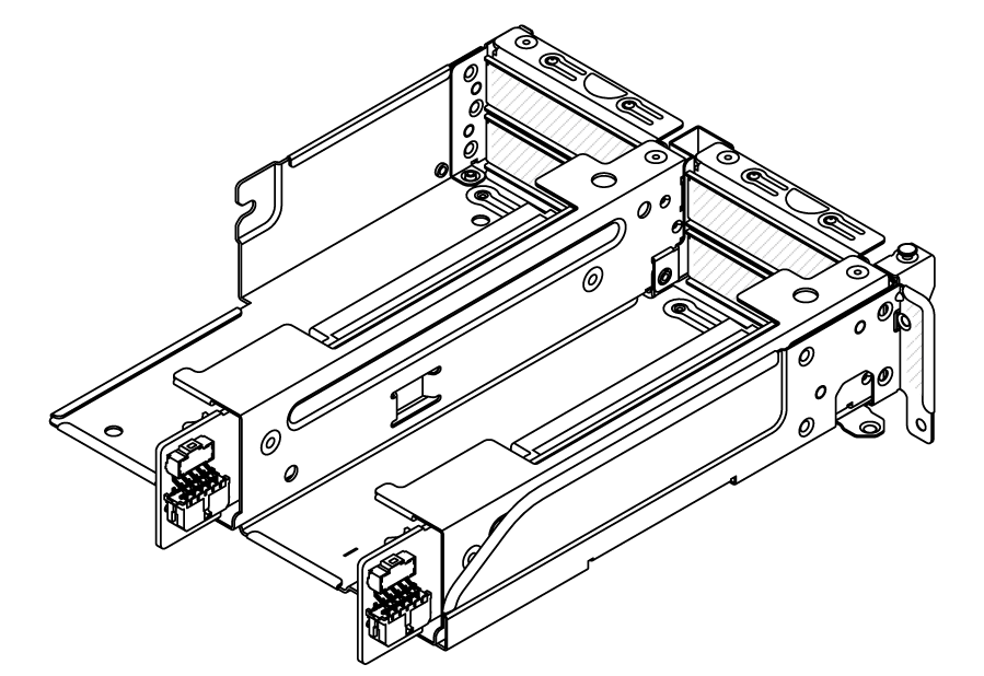
Riser 3/4 cage
Use this section to understand the cable routing for the riser 3/4 cage, which provide four low-profile (4LP) PCIe slots.
The following illustration shows the 4LP PCIe riser 3/4 cage. The riser card types vary by server model. For detailed information, see PCIe slots and PCIe adapters.
Power and sideband cable routing
The following illustration shows the power and sideband connections for x8/x8 PCIe riser 3 card and x8/x8 PCIe riser 4 card.
Figure 1. Riser 3/4 card power and sideband cable routing
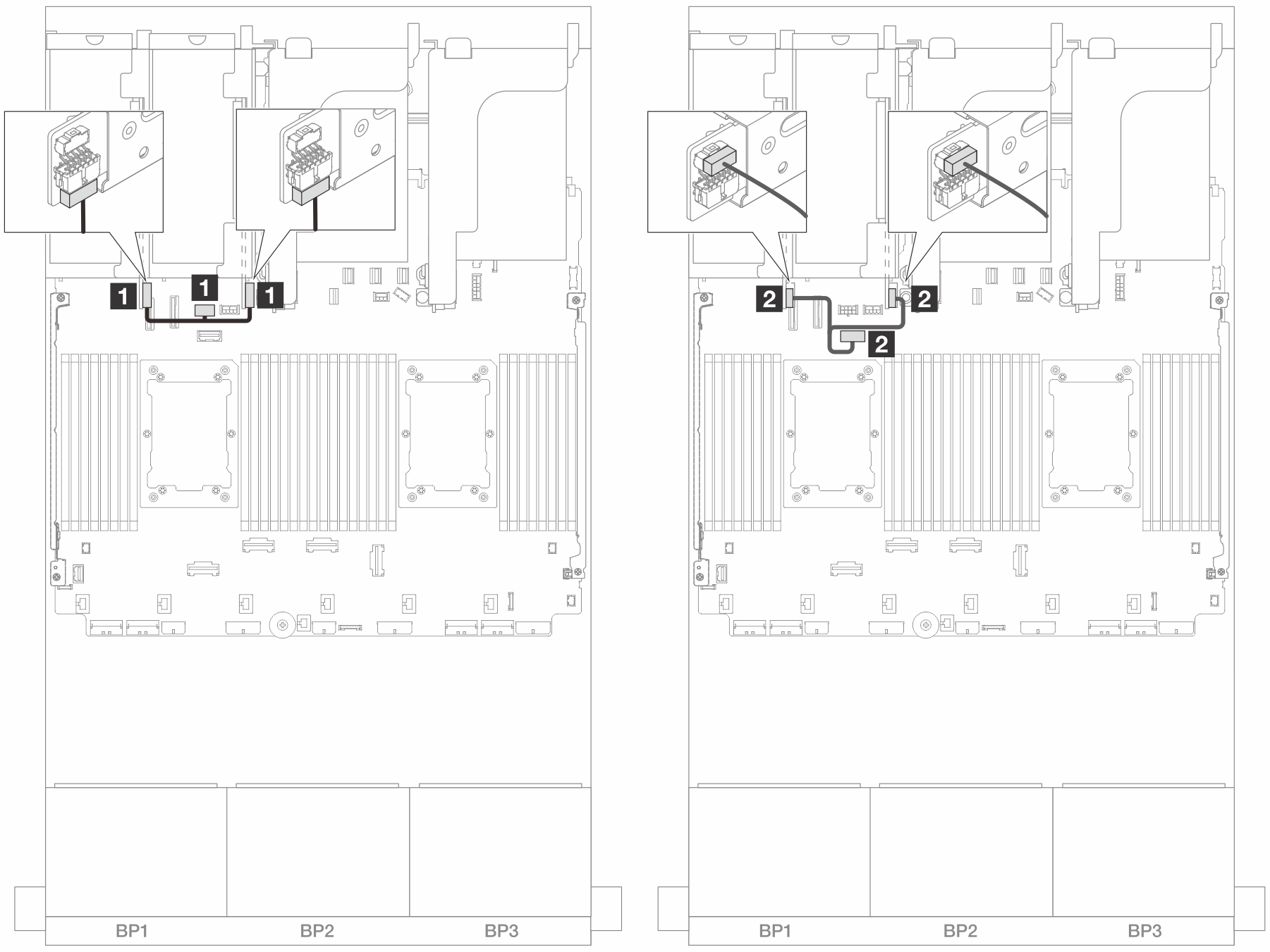
| From | To |
|---|---|
| 1 Power connector on the riser cards | Riser 3 power connector on the system board assembly |
| 2 Sideband connector on the riser cards | Riser 3 sideband connector on the system board assembly |
Signal cable connection
The following illustration shows the signal connections for x8/x8 PCIe riser 3 card and x8/x8 PCIe riser 4 card.
Figure 2. Cable routing in configurations without riser 5 and front OCP module
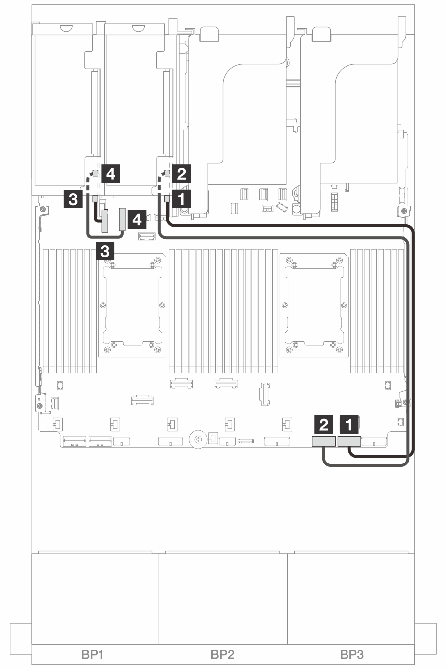
| From | To |
|---|---|
| 1 Swift connector 1 on riser 3 card | Onboard: PCIe 1 |
| 2 Swift connector 2 on riser 3 card | Onboard: PCIe 2 |
| 3 Swift connector 1 on riser 4 card | Onboard: PCIe 9 |
| 4 Swift connector 2 on riser 4 card | Onboard: PCIe 10 |
Figure 3. Cable routing in configurations with riser 5 and front OCP module when two processors are installed
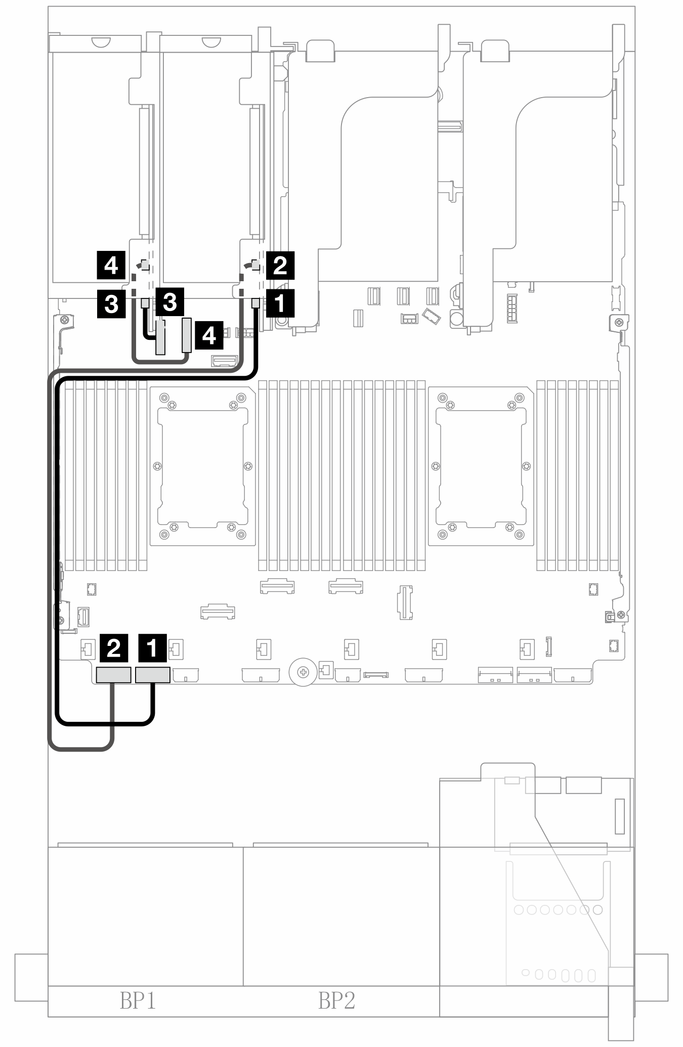
| From | To |
|---|---|
| 1 Swift connector 1 on riser 3 card | Onboard: PCIe 7 |
| 2 Swift connector 2 on riser 3 card | Onboard: PCIe 8 |
| 3 Swift connector 1 on riser 4 card | Onboard: PCIe 9 |
| 4 Swift connector 2 on riser 4 card | Onboard: PCIe 10 |
Give documentation feedback