M.2 drive backplanes
Use the section to understand the cable routing for the M.2 drive backplanes.
The server supports one of the following M.2 drive backplanes:
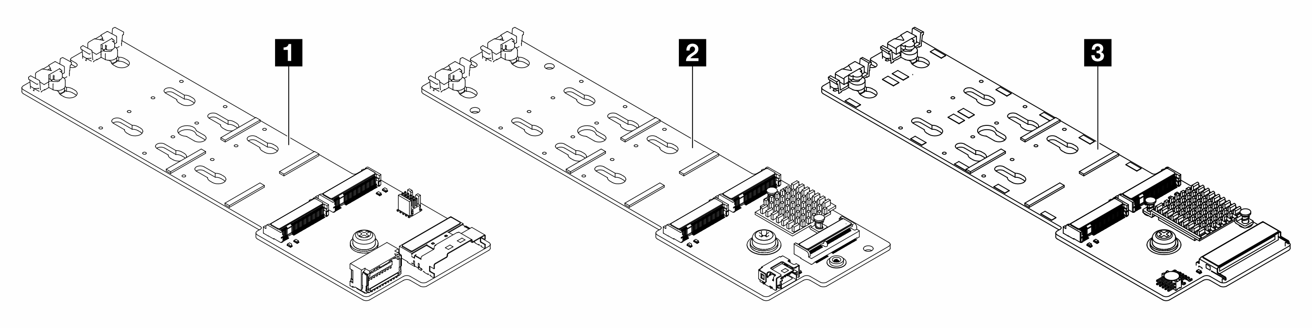 | |
1 | M.2 x4 non-RAID SATA/NVMe 2-bay backplane |
2 | M.2 x1 RAID NVMe 2-bay backplane |
3 | M.2 RAID SATA/NVME 2-bay backplane |
M.2 x4 non-RAID SATA/NVMe 2-bay backplane
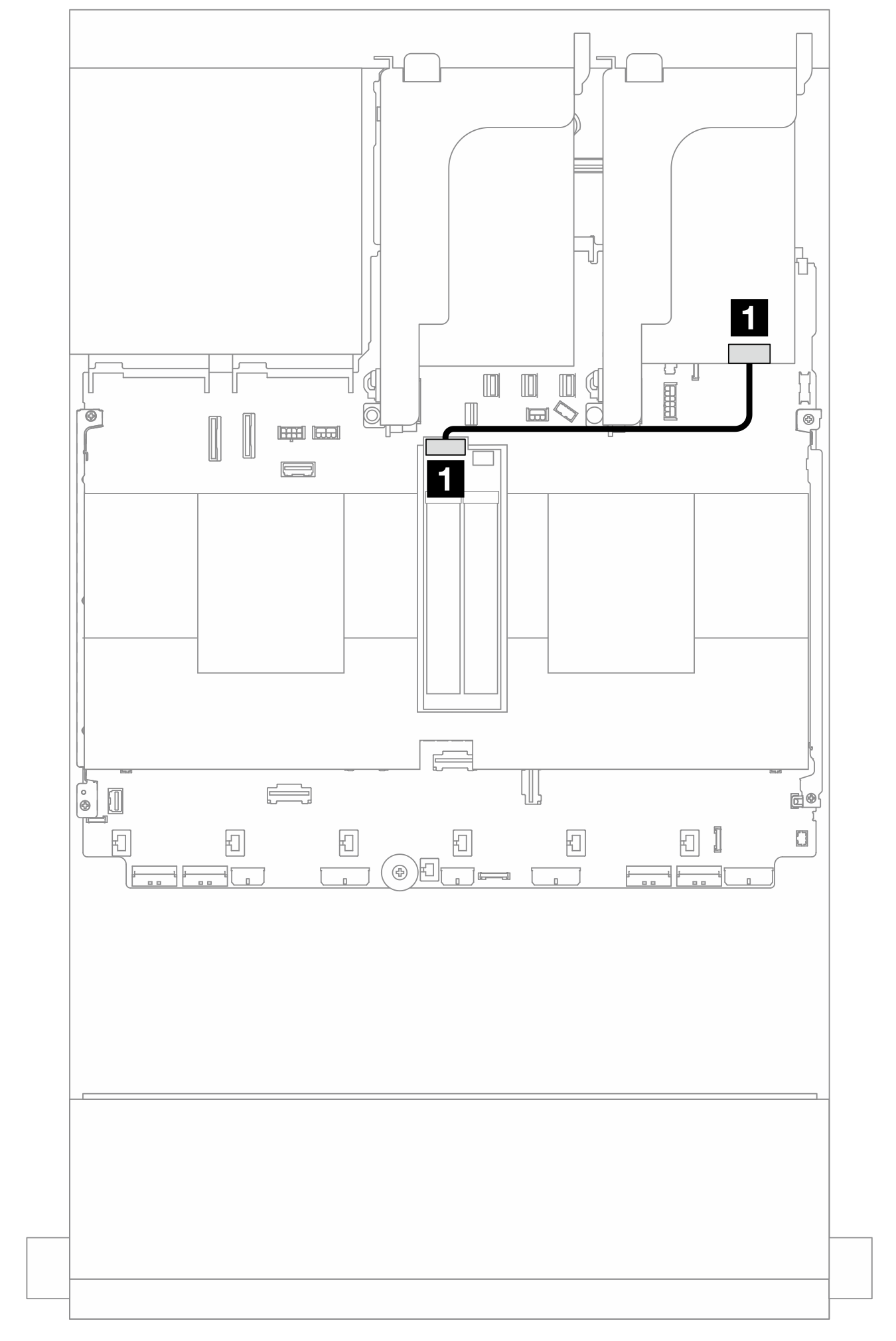
Power cable routing
Figure 1. Power cable routing
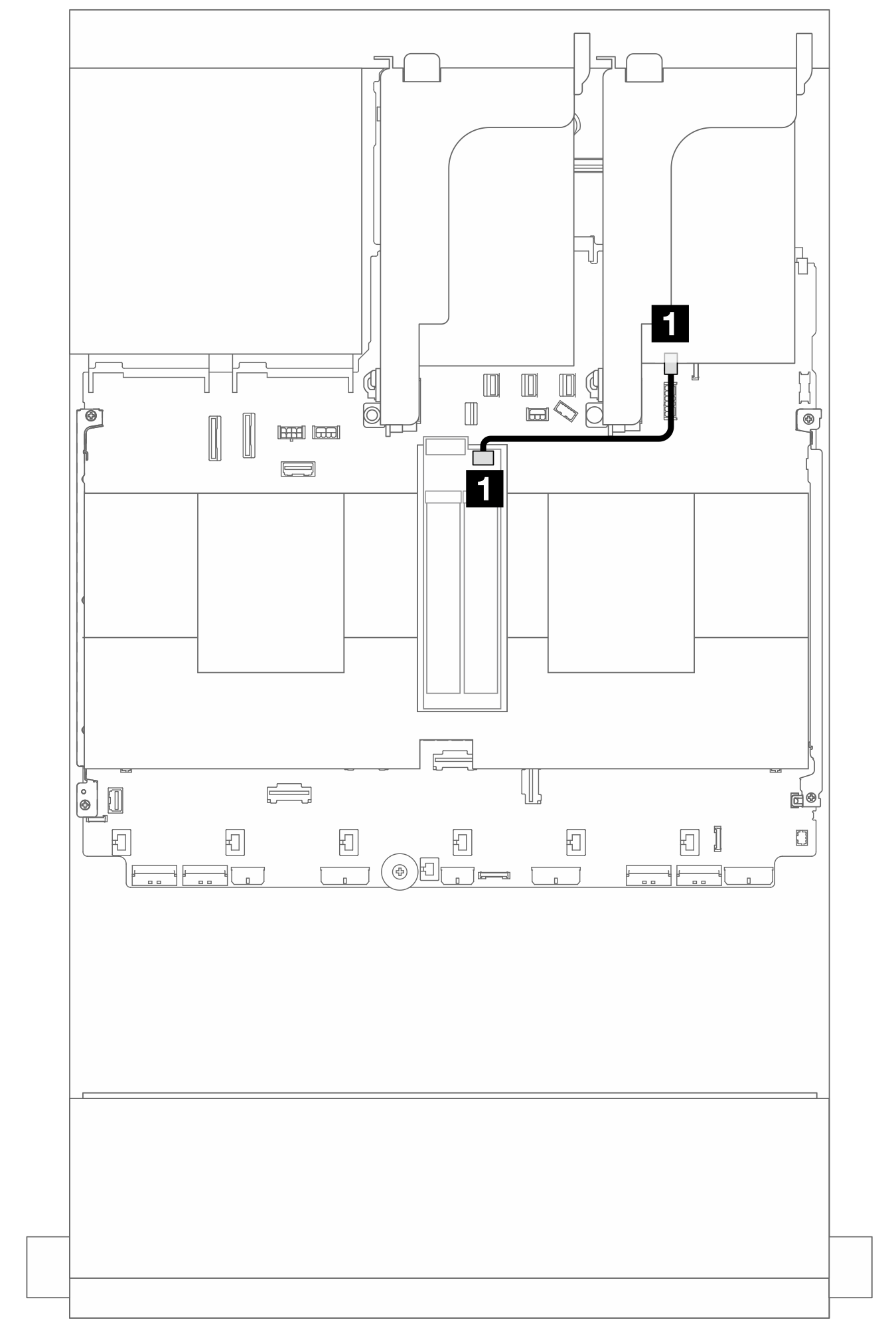
| From | To |
|---|---|
| 1 Power connector on the M.2 drive backplane | 1 M.2 power connector on the system board assembly |
Signal cable routing
The M.2 drive backplane supports SATA, NVMe, or RAID cable connection.
Figure 2. SATA cable routing
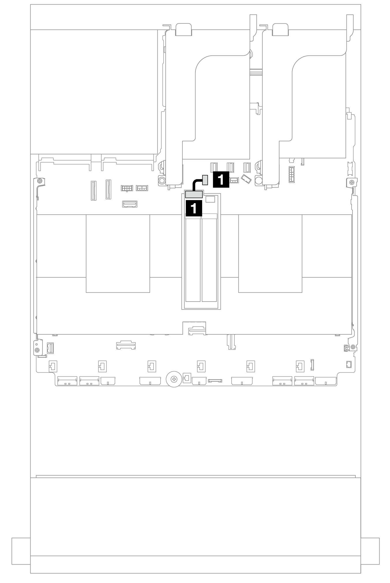
| From | To |
|---|---|
| 1 Signal connector on the M.2 drive backplane | 1 M.2/7mm backplane signal connector on the system board assembly |
Figure 3. NVMe cable routing
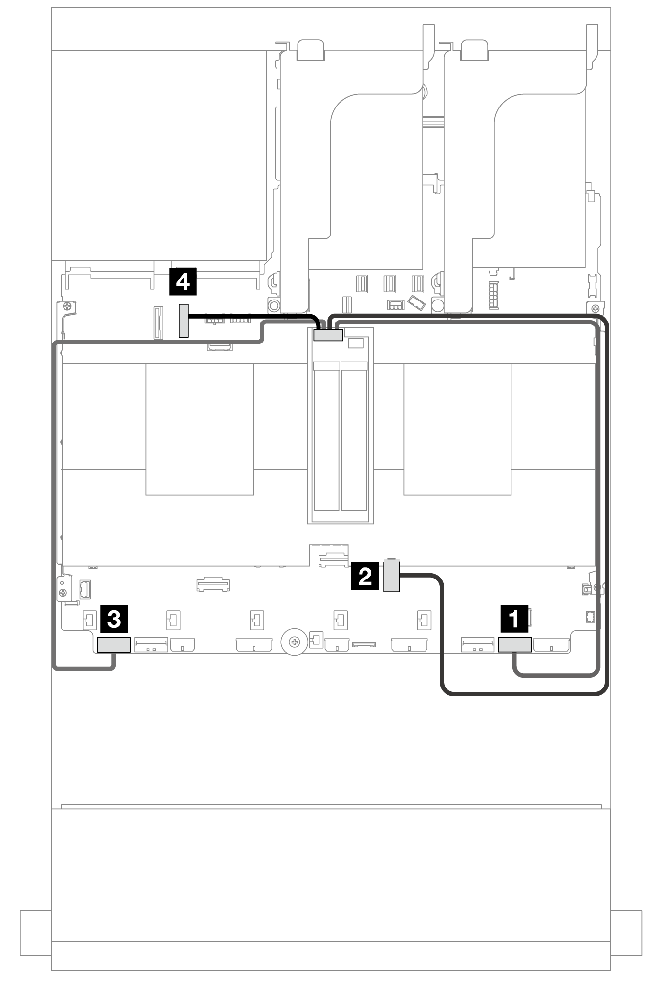
Note
The following illustration shows four NVMe cable connection options, but the four options are mutually exclusive. Select one of them based on your scenario.
| From | To |
|---|---|
| Signal connector on the M.2 drive backplane | 1 PCIe 1 |
| 2 PCIe 3 (one processor installed) | |
| 3 PCIe 8 | |
| 4 PCIe 10 |
Figure 4. RAID cable routing
| From | To |
|---|---|
| 1 Signal connector on the M.2 drive backplane | 1 8i adapter: C0 |
M.2 x1 RAID NVMe 2-bay backplane
Figure 5. Cable routing for the M.2 x1 RAID NVMe 2-bay backplane
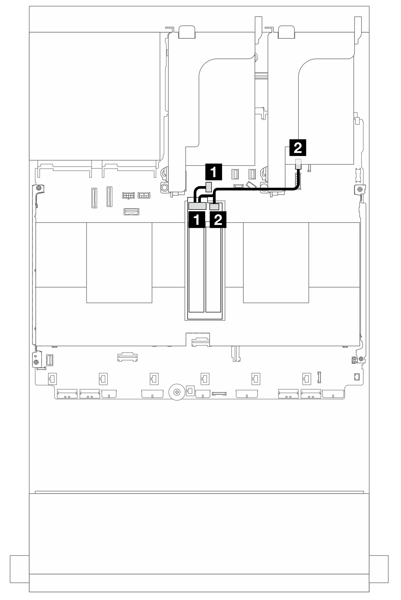
| From | To |
|---|---|
| 1 Signal connector on the M.2 drive backplane | 1 M.2/7mm backplane signal connector on the system board assembly |
| 2 Power connector on the M.2 drive backplane | 2 M.2 power connector on the system board assembly |
M.2 RAID SATA/NVME 2-bay backplane
Figure 6. Cable routing for the M.2 RAID SATA/NVME 2-bay backplane
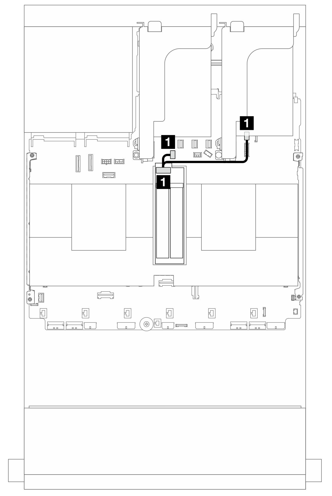
| From | To |
|---|---|
| 1 Connector on the M.2 drive backplane | 1
|
Give documentation feedback