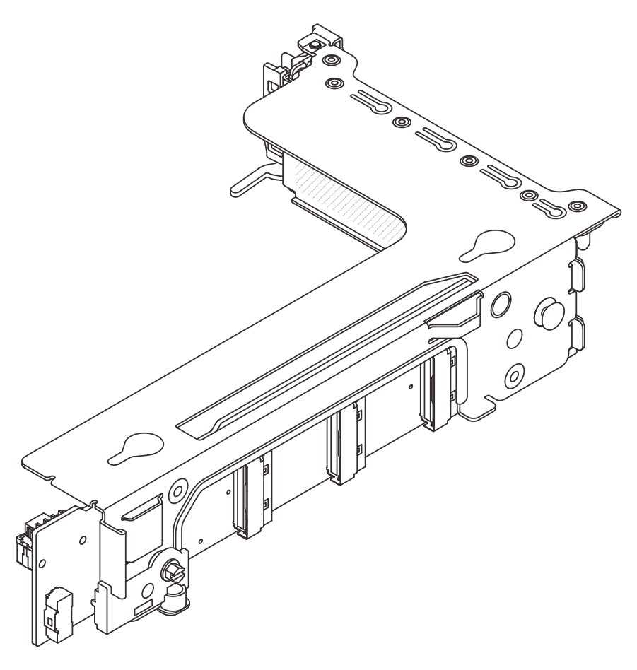
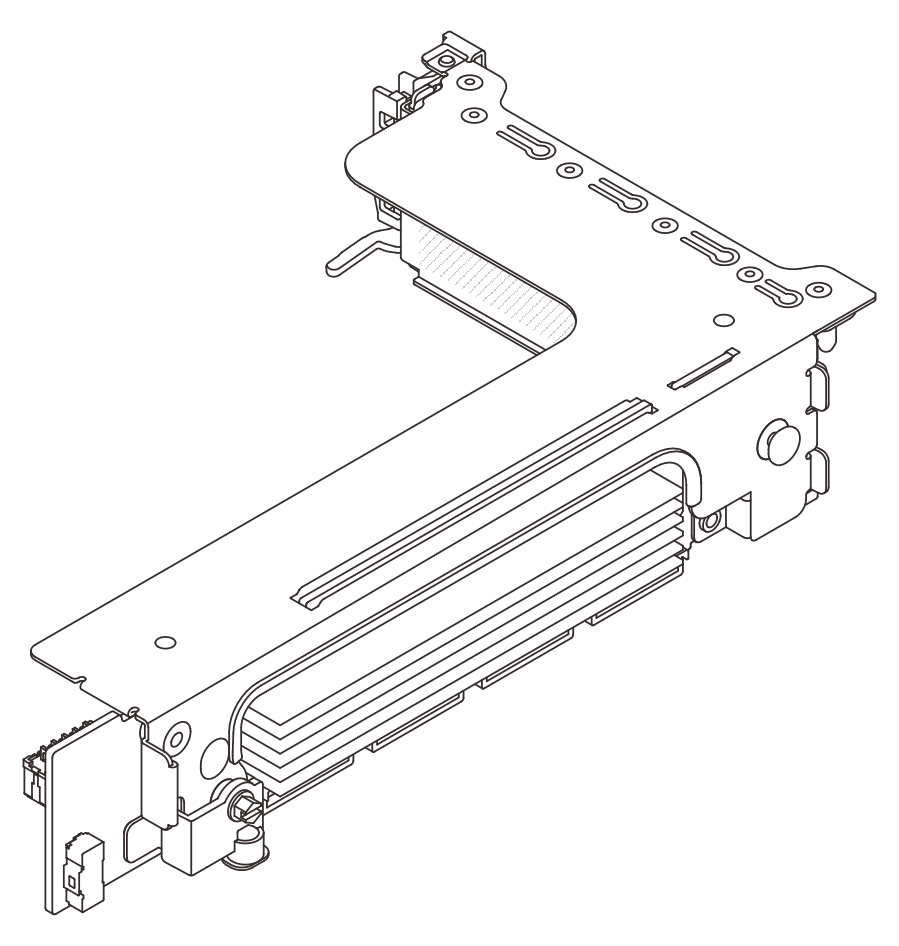
Riser 3 cage
Use this section to understand the cable routing for riser 3 cage.
The following illustrations show the PCIe riser 3 cages. The riser card types vary by server model. For detailed information, see PCIe slots and PCIe adapters.
| Gen 4 riser 3 cage | Gen 5 riser 3 cage |
 |  |
Riser card 3 power and sideband connection (Gen 4/Gen 5)
The power and sideband connections for x8/x8 PCIe riser card 3 and x16/x16 PCIe riser card 3 are the same.
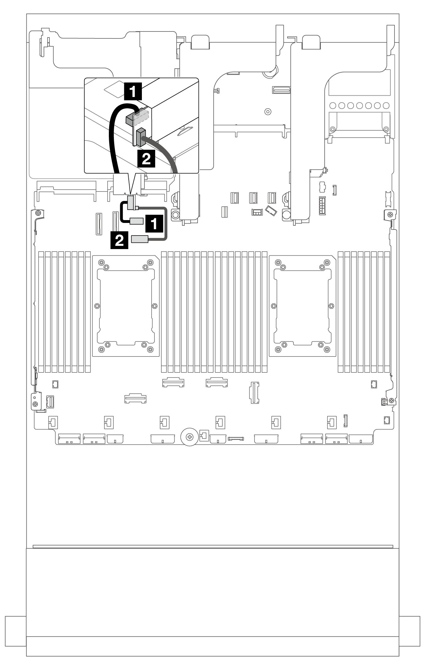
| From | To |
|---|---|
| 1 Power connector on the riser card | Riser 3 power connector on the system board assembly |
| 2 Sideband connector on the riser card | Riser 3 sideband connector on the system board assembly |
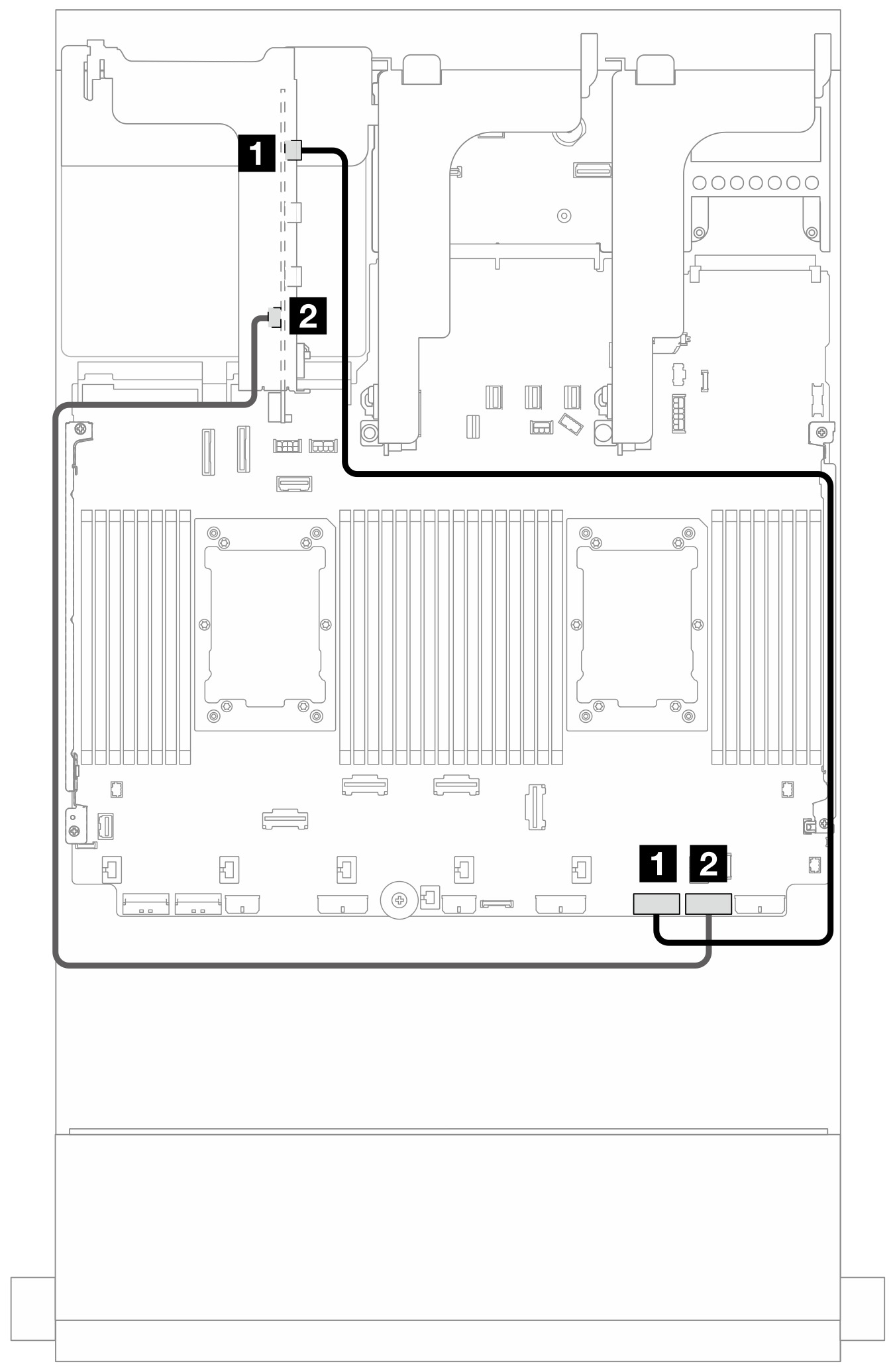
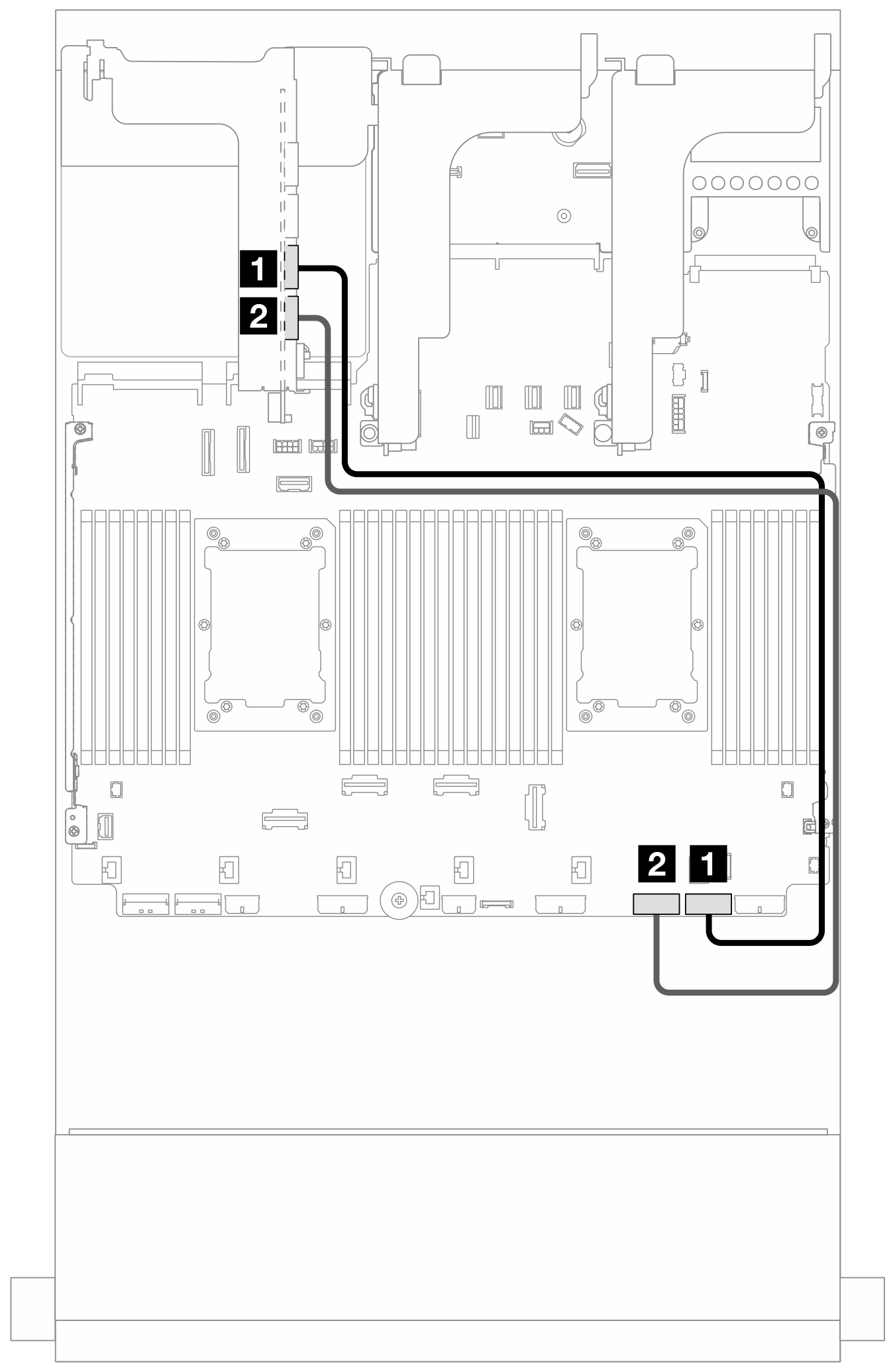
Riser card 3 (x8/x8 Gen 4 PCIe) signal cable connection
The following illustration shows the signal cable connections for the x8/x8 Gen 4 PCIe riser card 3.
Figure 2. Cable routing when two processors installed 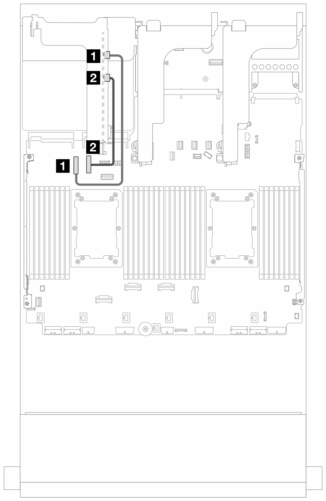 | Figure 3. Cable routing when one processor installed 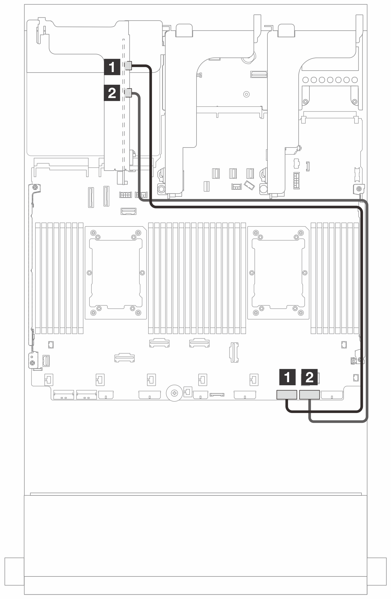 | ||
| From | To | From | To |
| 1 MCIO 1 on the riser card | PCIe connector 9 on the system board assembly | 1 MCIO 1 on the riser card | PCIe connector 2 on the system board assembly |
| 2 MCIO 2 on the riser card | PCIe connector 10 on the system board assembly | 2 MCIO 2 on the riser card | PCIe connector 1 on the system board assembly |
Riser card 3 (x16/x16 Gen 4 PCIe) signal cable connection
The following illustration shows the signal cable connections for the x16/x16 Gen 4 PCIe riser card 3.
Cable routing when two processors installed
Figure 4. Cable routing in configurations without riser 5 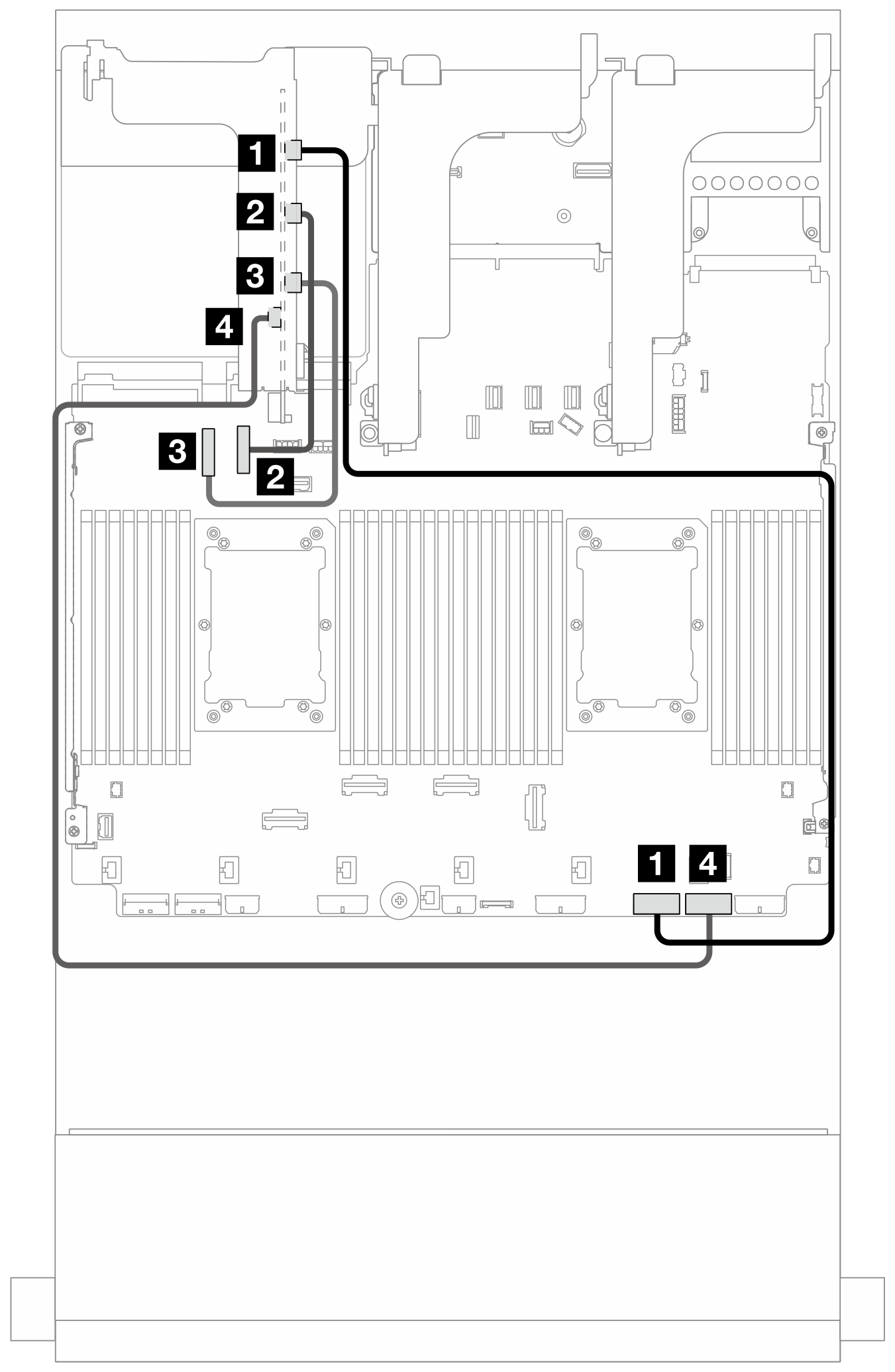 | Figure 5. Cable routing in configurations with riser 5 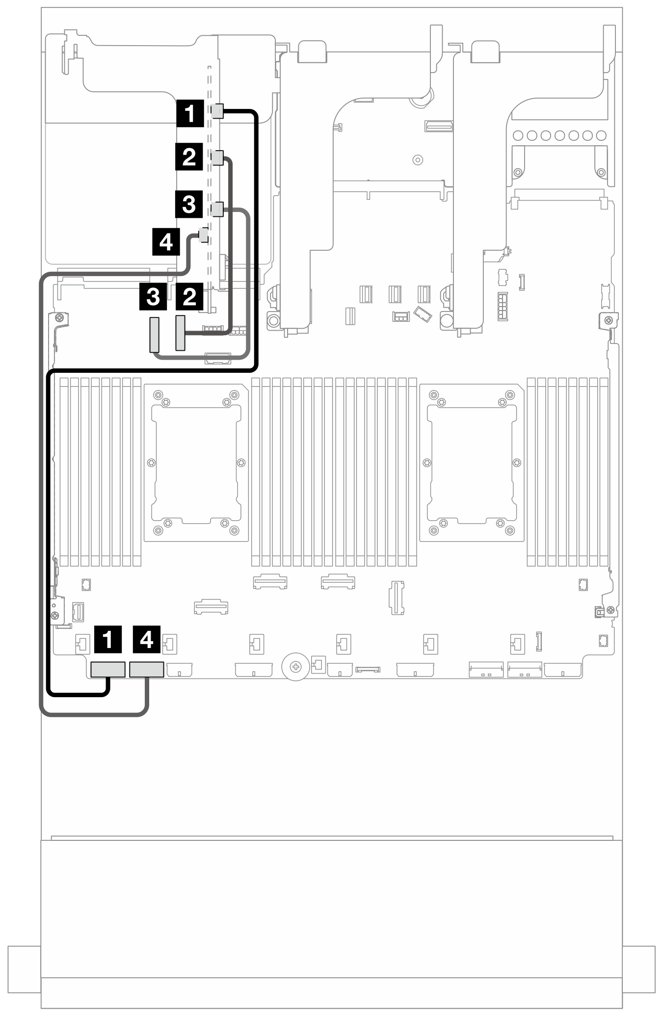 | ||
| From | To | From | To |
| 1 MCIO 1 on the riser card | PCIe connector 2 on the system board assembly | 1 MCIO 1 on the riser card | PCIe connector 8 on the system board assembly |
| 2 MCIO 2 on the riser card | PCIe connector 10 on the system board assembly | 2 MCIO 2 on the riser card | PCIe connector 10 on the system board assembly |
| 3 MCIO 3 on the riser card | PCIe connector 9 on the system board assembly | 3 MCIO 3 on the riser card | PCIe connector 9 on the system board assembly |
| 4 MCIO 4 on the riser card | PCIe connector 1 on the system board assembly | 4 MCIO 4 on the riser card | PCIe connector 7 on the system board assembly |
| From | To |
|---|---|
| 1 MCIO 1 on the riser card | PCIe connector 2 on the system board assembly |
| 2 MCIO 4 on the riser card | PCIe connector 1 on the system board assembly |
Riser card 3 (x8/x8 Gen 5 PCIe) signal cable connection
The following illustration shows the signal cable connections for the x8/x8 Gen 5 PCIe riser card 3.
Figure 7. Cable routing when two processors installed 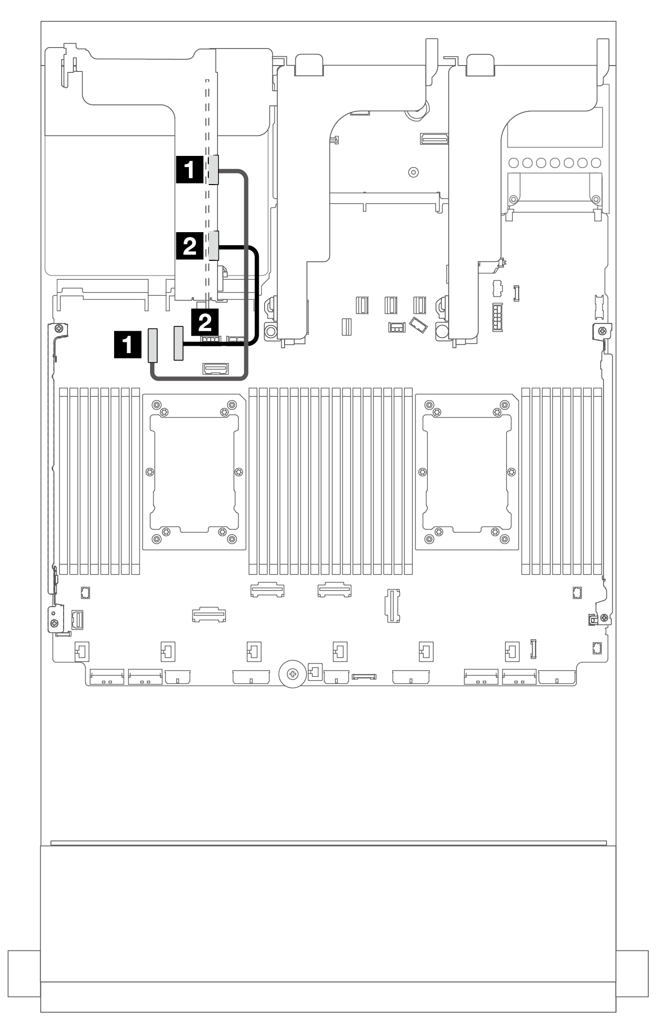 | Figure 8. Cable routing when one processor installed 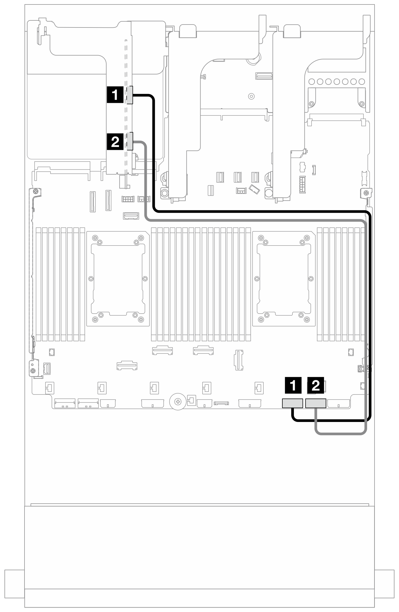 | ||
| From | To | From | To |
| 1 MCIO 1 on the riser card | PCIe connector 9 on the system board assembly | 1 MCIO 1 on the riser card (Gen 4) | PCIe connector 2 on the system board assembly |
| 2 MCIO 3 on the riser card | PCIe connector 10 on the system board assembly | 2 MCIO 3 on the riser card (Gen 5) | PCIe connector 1 on the system board assembly |
Riser card 3 (x16/x16 Gen 5 PCIe) signal cable connection
The following illustration shows the signal cable connections for the x16/x16 Gen 5 PCIe riser card 3.
Cable routing when two processors installed
Figure 9. Cable routing in configurations without riser 5 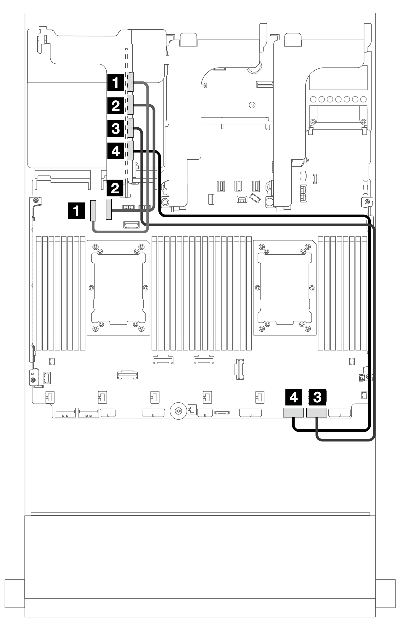 | Figure 10. Cable routing in configurations with riser 5 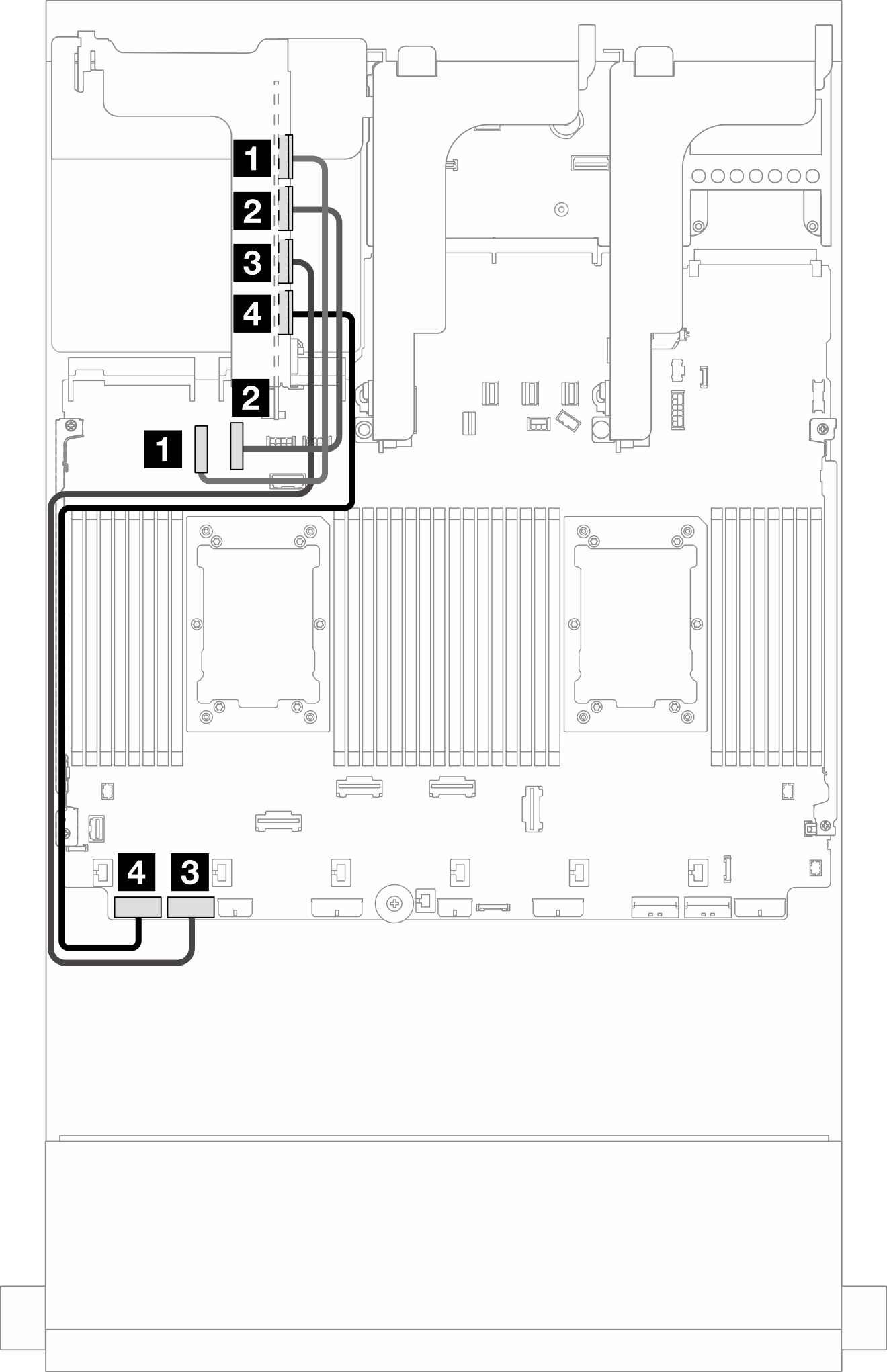 | ||
| From | To | From | To |
| 1 MCIO 1 on the riser card | PCIe connector 9 on the system board assembly | 1 MCIO 1 on the riser card | PCIe connector 9 on the system board assembly |
| 2 MCIO 2 on the riser card | PCIe connector 10 on the system board assembly | 2 MCIO 2 on the riser card | PCIe connector 10 on the system board assembly |
| 3 MCIO 3 on the riser card | PCIe connector 1 on the system board assembly | 3 MCIO 3 on the riser card | PCIe connector 7 on the system board assembly |
| 4 MCIO 4 on the riser card | PCIe connector 2 on the system board assembly | 4 MCIO 4 on the riser card | PCIe connector 8 on the system board assembly |
| From | To |
|---|---|
| 1 MCIO 3 on the riser card | PCIe connector 1 on the system board assembly |
| 2 MCIO 4 on the riser card | PCIe connector 2 on the system board assembly |