Install a power supply unit
Use this information to install a power supply.
About this task
The server is shipped with only one power supply by default. In this case, the power supply is non-hot-swap and before removing it, you must turn off the server first. To support redundancy mode or hot-swap, install an additional hot-swap power supply.
- If you are replacing the existing power supply with a new power supply:
Use Lenovo Capacity Planner to calculate the required power capacity for what is configured for your server. More information about Lenovo Capacity Planner is available at:
- Ensure that the devices that you are installing are supported. For a list of supported optional devices for the server, go to: Lenovo ServerProven website
Attach the power information label that comes with this option onto the existing label near the power supply.
Figure 1. Example power supply unit label on the top cover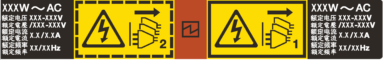
Read Installation Guidelines and Safety inspection checklist to ensure that you work safely.
Prevent exposure to static electricity, which might lead to system halt and loss of data, by keeping static-sensitive components in their static-protective packages until installation, and handling these devices with an electrostatic-discharge wrist strap or other grounding system.
Procedure
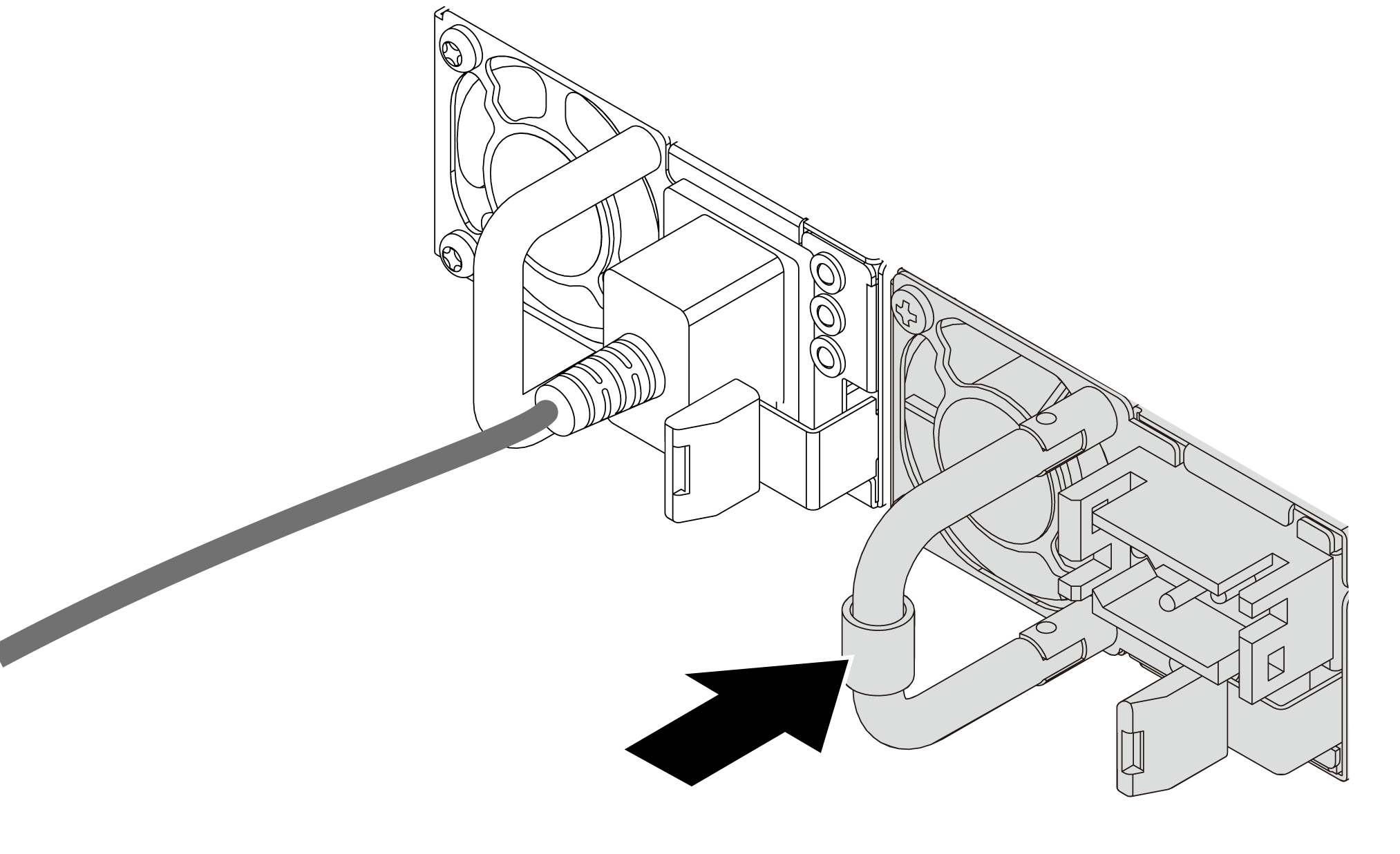
- Slide the new hot-swap power supply into the bay until it snaps into position.Figure 2. Hot-swap power supply installation
- Connect the power supply unit to a properly grounded electrical outlet.
For AC power supply units:
Connect one end of the power cord to the power connector on the power supply unit.
Connect the other end of the power cord to a properly grounded electrical outlet.
For –48V DC power supply units:
Use a slotted screwdriver to loosen the 3 captive screws on the power supply terminal block.
- Check the type label on the power supply block and each power cord.
Type PSU terminal block Power cord Input 
-Vin Ground 
GND Input 
RTN Face the groove side of each power cord pin upwards, plug the pins into corresponding holes on the power block, use the table above for guidance, and ensure that the pins find correct slots.
Tighten the captive screws on the power block, and ensure that the screws and cord pins are secured in place and no bare metal parts show.
Connect the other end of the cables to a properly grounded electrical outlet, and ensure that the cable ends find correct outlets.
After you finish
If you have adjusted the CMA to gain access to the power supply bay, properly readjust the CMA back in place.
If the server is turned off, turn on the server. Ensure that both the power input LED and the power output LED on the power supply are lit, indicating that the power supply is operating properly.
Demo video