Install the manifold (in-row system)
Follow the instructions to install the manifold in an in-row direct water cooling system.
About this task
This task must be operated by trained technicians that are certified by Lenovo Service. Do not attempt to remove or install the part without proper training and qualification.
The liquid might cause irritation to the skin and eyes. Avoid direct contact with the liquid.



Read Installation Guidelines and Safety inspection checklist to ensure that you work safely.
Power off the server and peripheral devices and disconnect the power cords and all external cables. See Power off the server.
Prevent exposure to static electricity, which might lead to system halt and loss of data, by keeping static-sensitive components in their static-protective packages until installation, and handling these devices with an electrostatic-discharge wrist strap or other grounding system.
Ensure proper handling procedures are followed when working with any chemically treated liquid used in the rack cooling system. Ensure that material safety data sheets (MSDS) and safety information are provided by the liquid chemical treatment supplier and that proper personal protective equipment (PPE) is available as recommended by the liquid chemical treatment supplier. Protective gloves and eyewear may be recommended as a precaution.
This task requires two or more people.
Procedure
- Install the manifold.Figure 1. Installing the manifold

 Hold the manifold with both hands, and mount it onto the rack cabinet.
 Align the spools with holes, and clutch the cabinet.
NoteFor more information about the rack cabinet, seeThinkSystem Heavy Duty Full Depth Rack Cabinets User Guide. - Install the quick connect plug to the manifolds.Figure 2. Installing the quick connect plug

- Remove the rubber quick connect plug covers from the ports on the manifold.
- Connect the plug to the manifold port.
- Install the hose kit to the manifold.Figure 3. Installing the hose kit
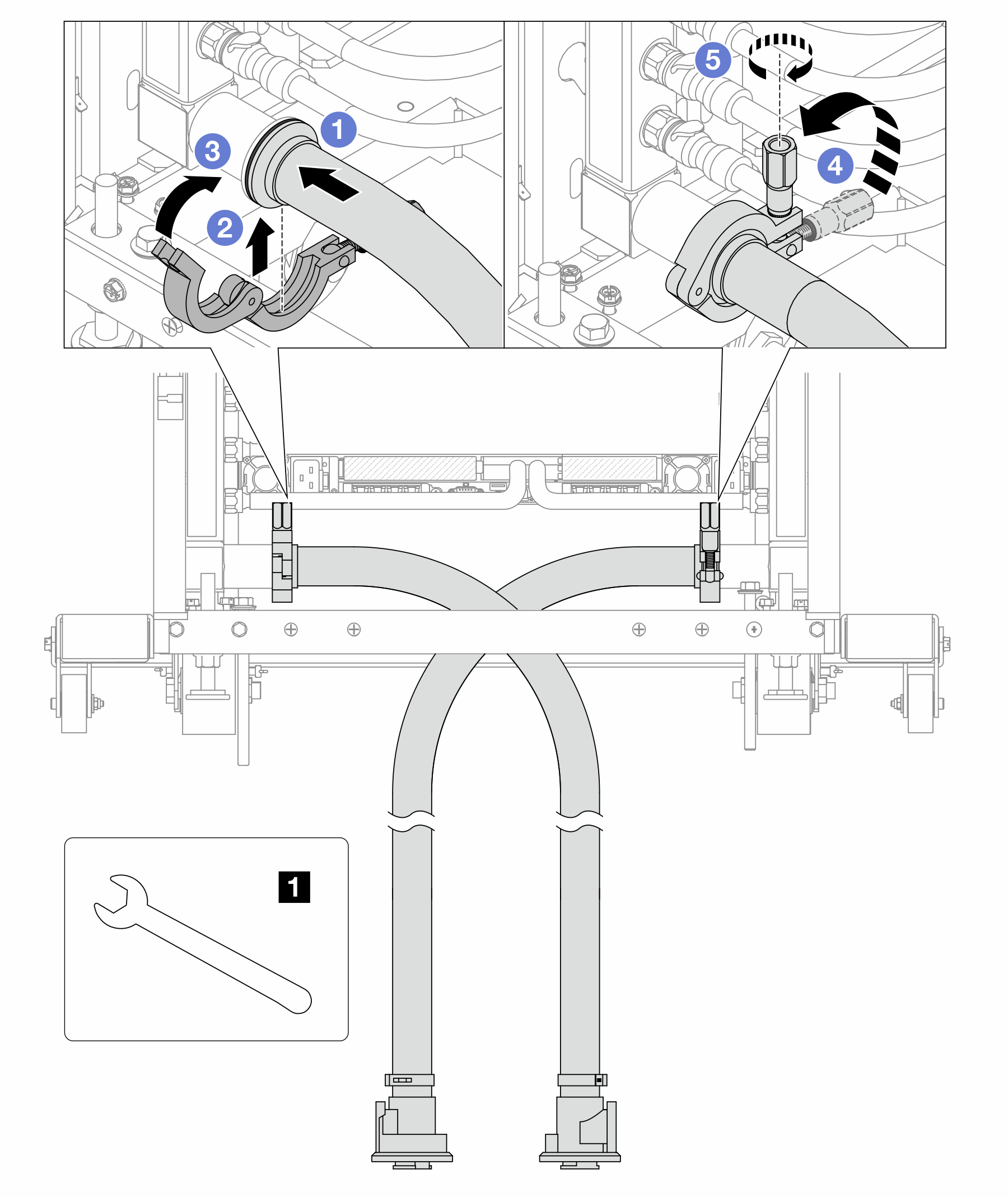
1 17 mm wrench - Connect the hose kits to both manifolds.
- Wrap the interface around with the clamp.
 Close the clamp.
 Lift the screw upright.
 Tighten the screw and make sure that it is secured.
- Install the bleeder kit to the manifold supply side.Figure 4. Installing the bleeder kit to the supply side
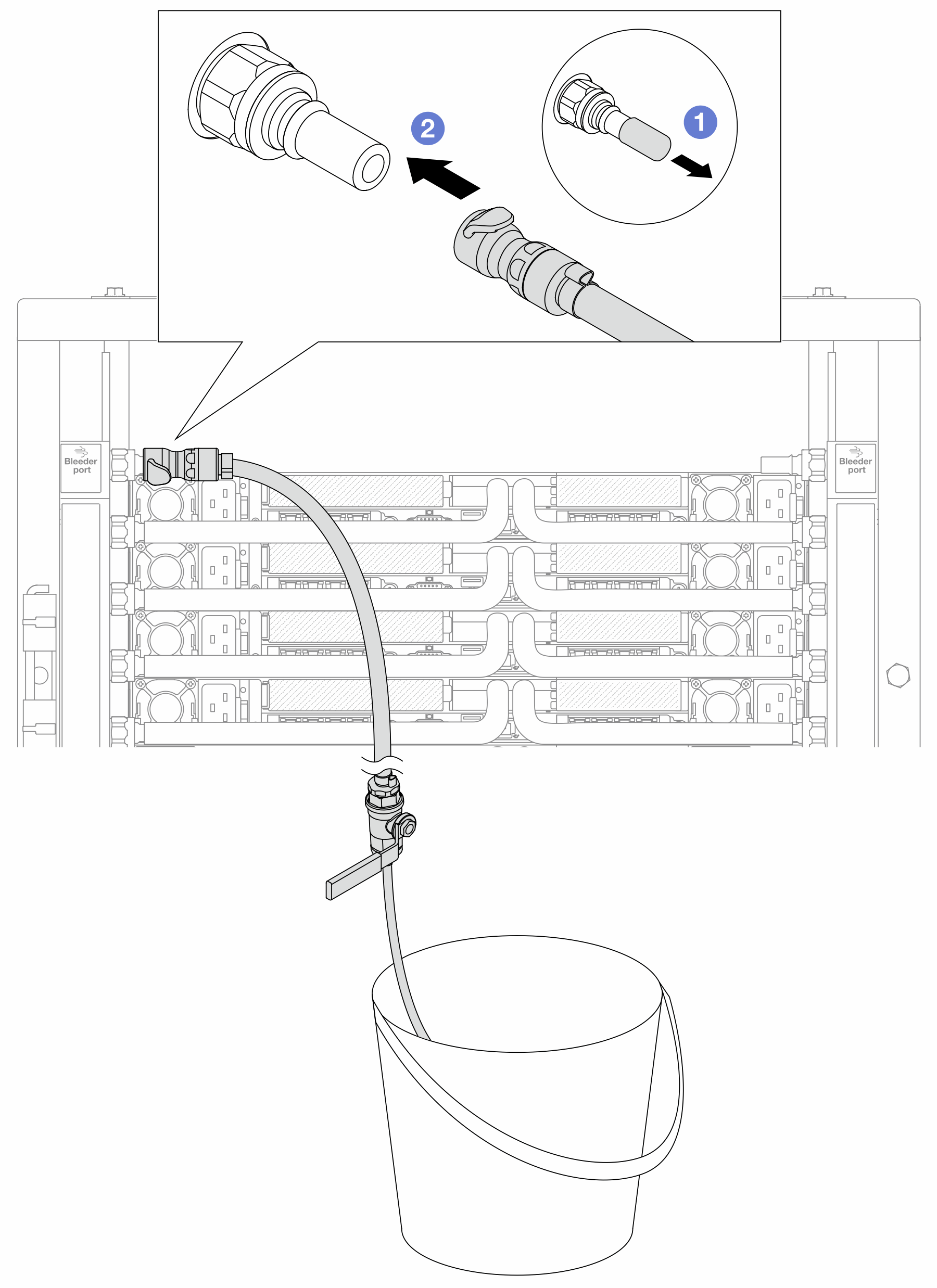
- Remove the rubber quick connect plug covers from the ports on the manifold.
- Plug the bleeder kit to the manifold.
- To push the air out of the manifold supply side, connect facility supply to manifold return.Figure 5. Facility supply to manifold return
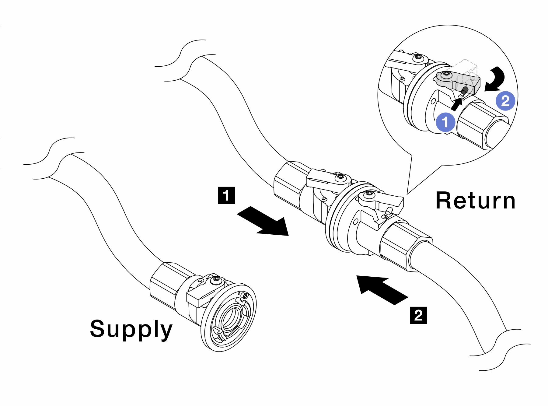
- Press the button on the ball valve switch.
- Rotate both switches open and stop at around 1/4 of 90 degrees.Attention
Open the ball valves on 1 manifold return side and 2 facility supply side, while keep manifold supply side closed.
Do not fully open the ball valves, or the water flow gets too rapid to contain.
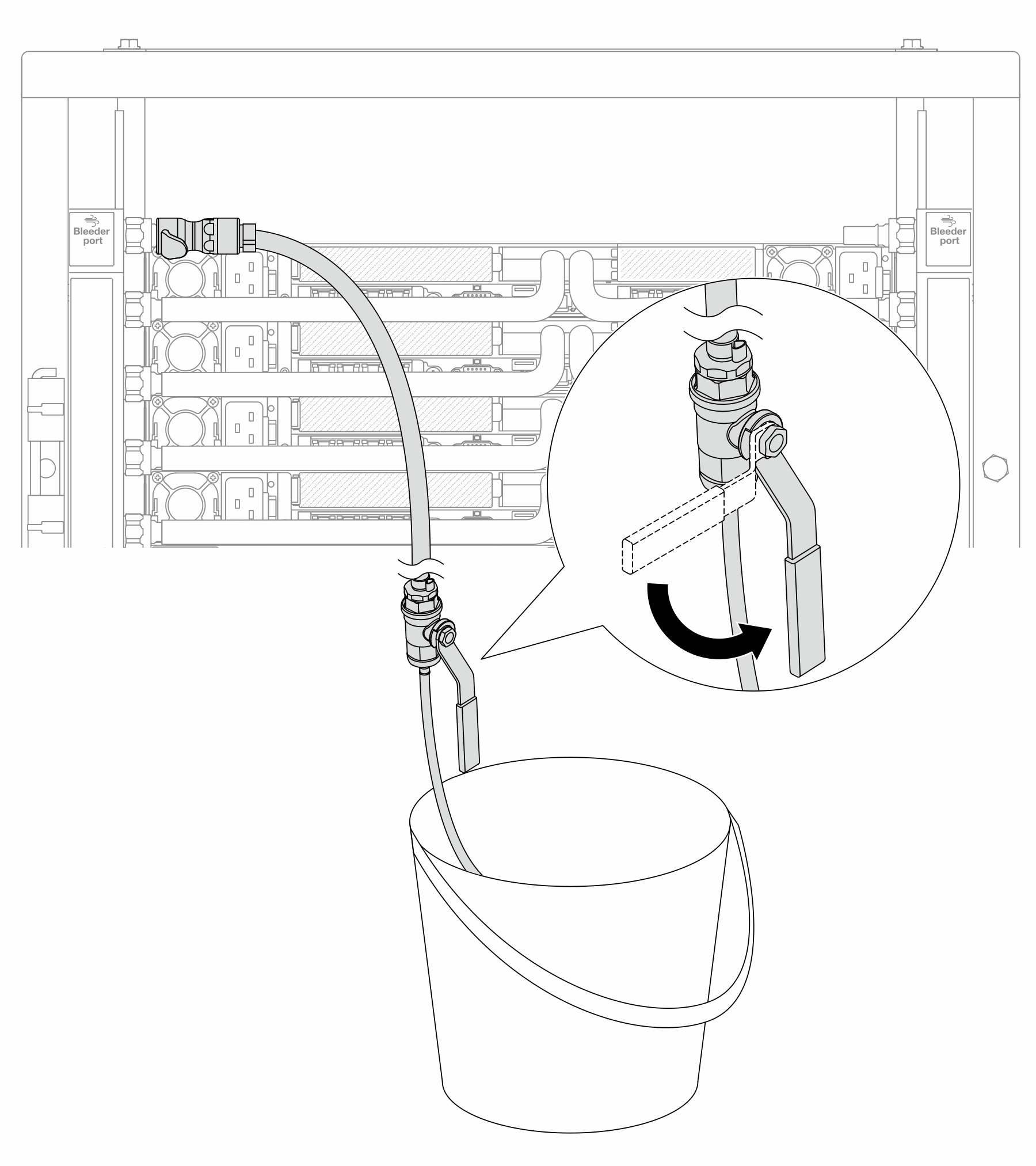
- Slowly open the bleeder valve to conduct the air out of the hose. Close the bleeder valve once a steady stream of water flows into the bucket or there are only minimal bubbles in the bleeder hose.Figure 6. Opening the bleeder valve on the supply side
- Install the bleeder kit to the manifold return side.Figure 7. Installing the bleeder kit on the return side
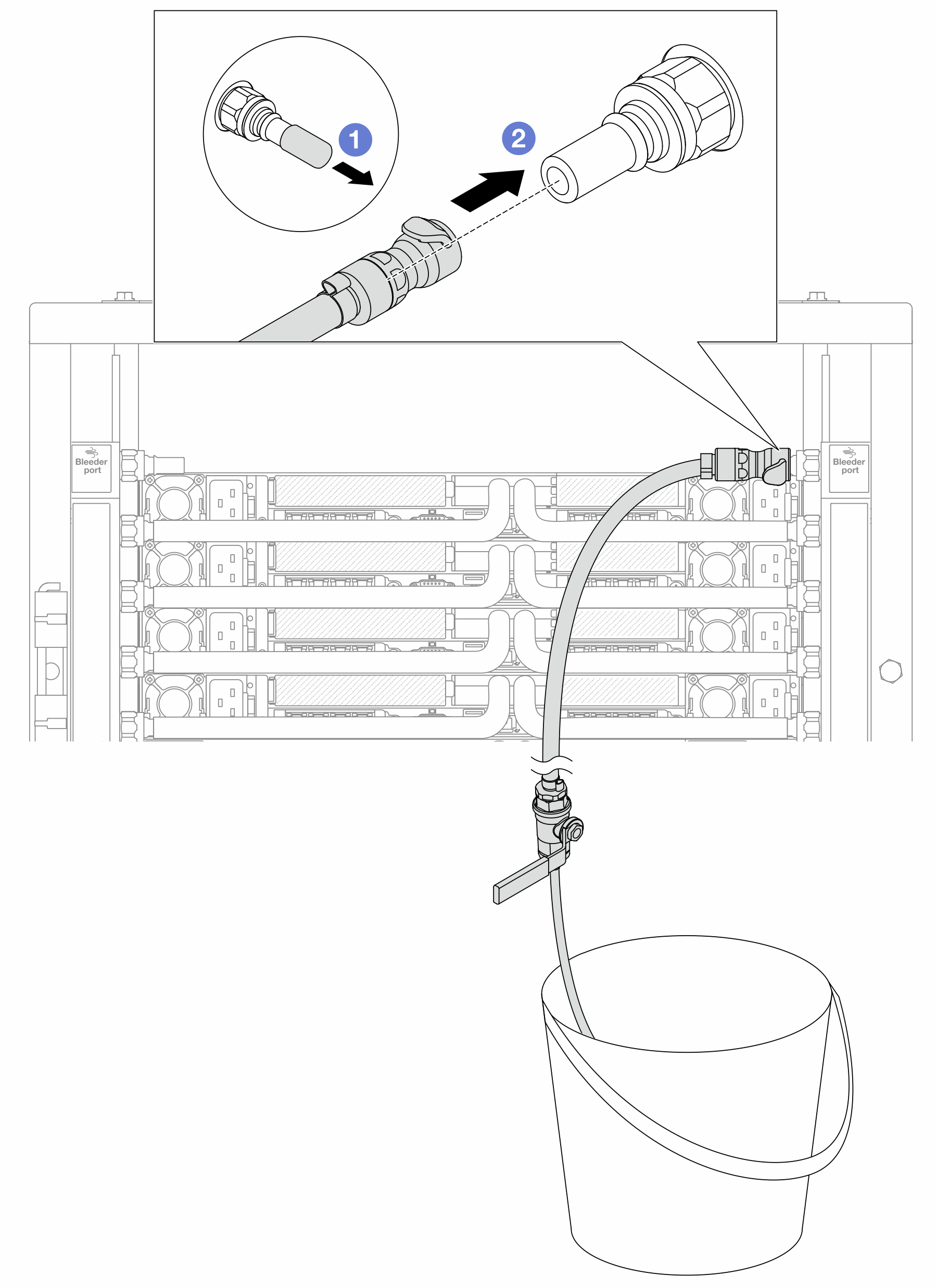
- Remove the rubber quick connect plug covers from the ports on the manifold.
- Plug the bleeder kit to the manifold.
- To push the air out of the manifold return side, connect facility supply to manifold supply.Figure 8. Facility supply to manifold supply
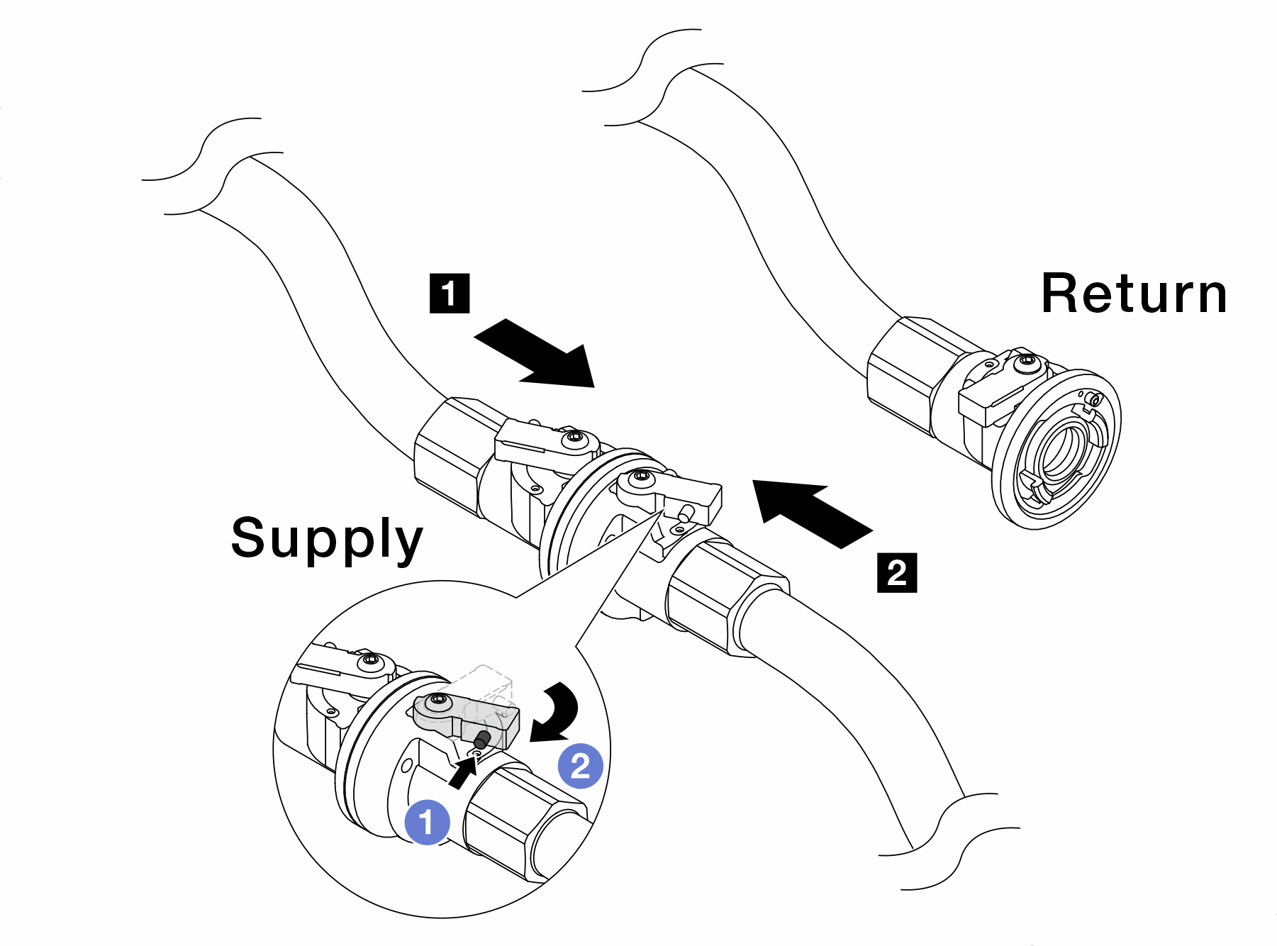
- Press the button on the ball valve switch.
- Rotate both switches open and stop at around 1/4 of 90 degrees.Attention
Open the ball valves on 1 manifold supply side and 2 facility supply side, while keep manifold return side closed.
Do not fully open the ball valves, or the water flow gets too rapid to contain.
- Slowly open the bleeder valve to conduct the air out of the hose. Close the bleeder valve once a steady stream of water flows into the bucket or there are only minimal bubbles in the bleeder hose.Figure 9. Opening the bleeder valve on the return side
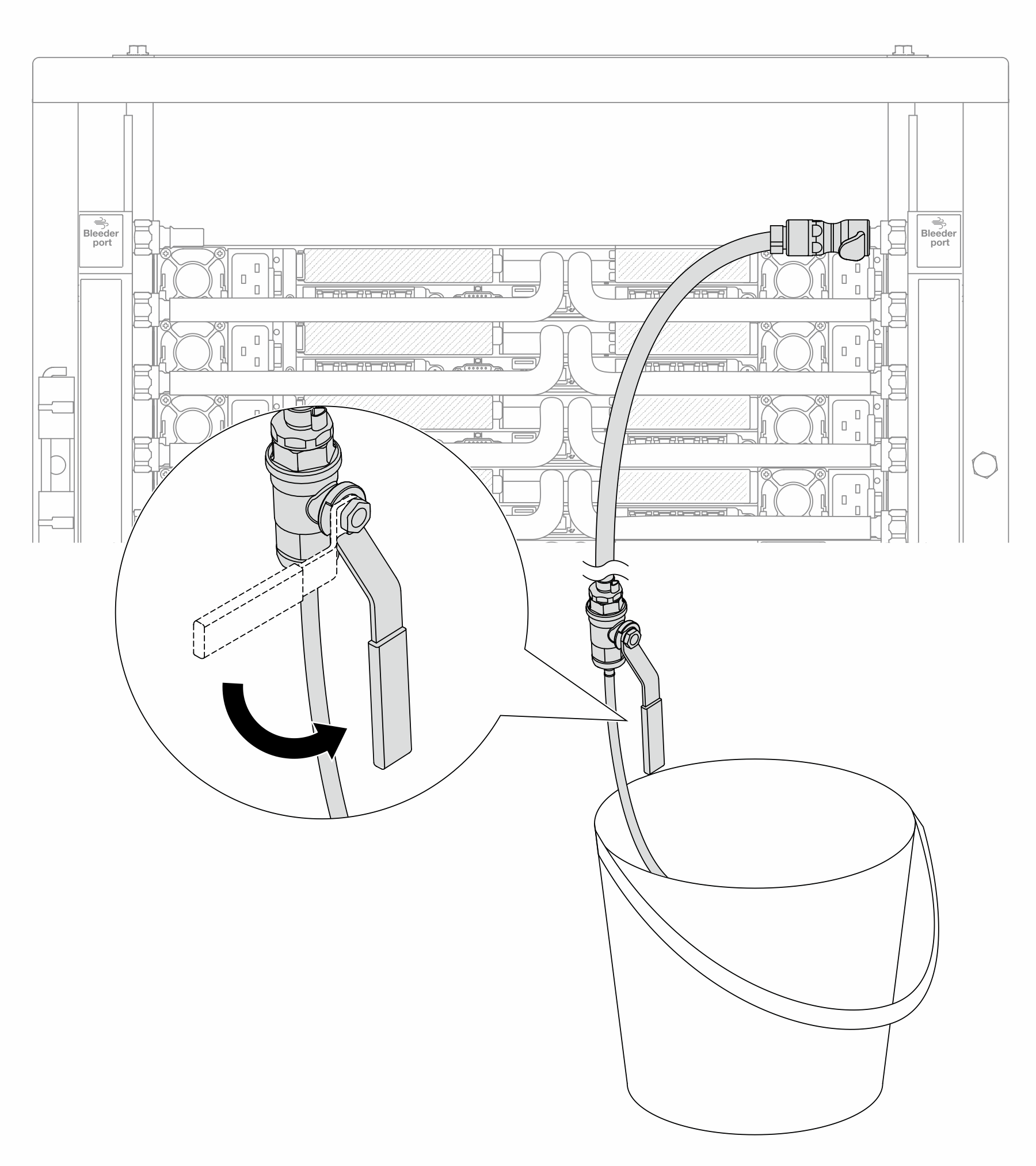
- (For precaution) To make sure that the air inside is as little as possible, re-install the bleeder kit back to manifold supply side and do it one more time. Close the bleeder valve once a steady stream of water flows into the bucket or there are only minimal bubbles in the bleeder hose.Figure 10. Opening the bleeder valve on the supply side
- Once completed, connect the supply and return of manifold and facility correspondingly. Fully open all connections on both supply and return sides.Figure 11. Opening ball valves
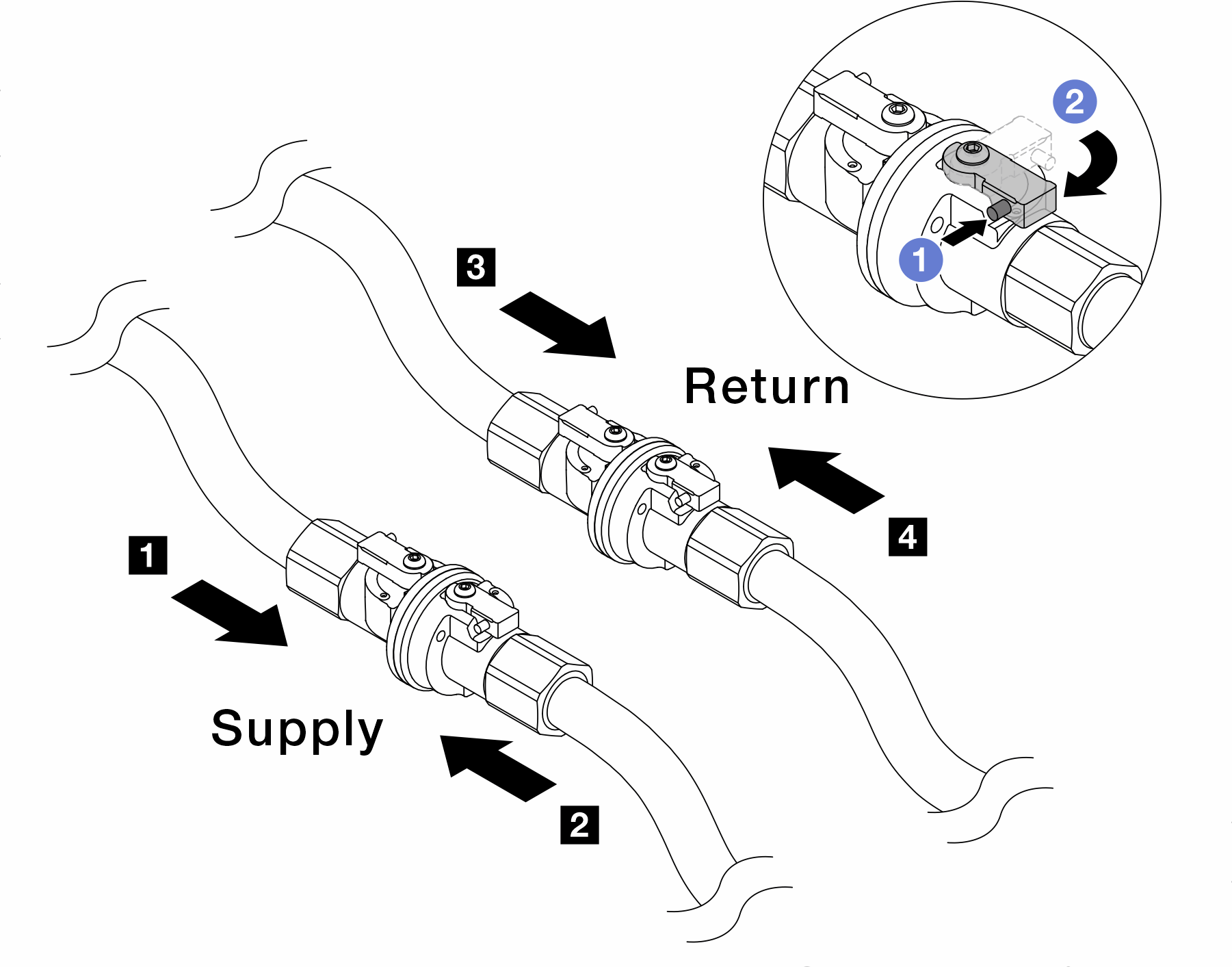 Note
Note1 Manifold supply connects to 2 facility supply 3 Manifold return connects to 4 facility return - Press the button on the ball valve switch.
- Rotate the switch to fully open the valves as illustrated above.
Complete the parts replacement. See Complete the parts replacement.