Install the Lenovo Processor Neptune Core Module
Follow the instructions in this section to install the Processor Neptune Core Module.
This task must be operated by trained technicians that are certified by Lenovo Service. Do not attempt to remove or install the part without proper training and qualification.
Contact Lenovo Professional Services team for help when installing the part for the first time.
About this task

Read Installation Guidelines and Safety inspection checklist to ensure that you work safely.
Power off the server and peripheral devices and disconnect the power cords and all external cables. See Power off the server.
Prevent exposure to static electricity, which might lead to system halt and loss of data, by keeping static-sensitive components in their static-protective packages until installation, and handling these devices with an electrostatic-discharge wrist strap or other grounding system.
| Torque screwdriver type list | Screw Type |
|---|---|
| Torx T30 head screwdriver | Torx T30 screw |
Procedure
- Install the hose holder to the chassis.Figure 1. Installing the hose holder
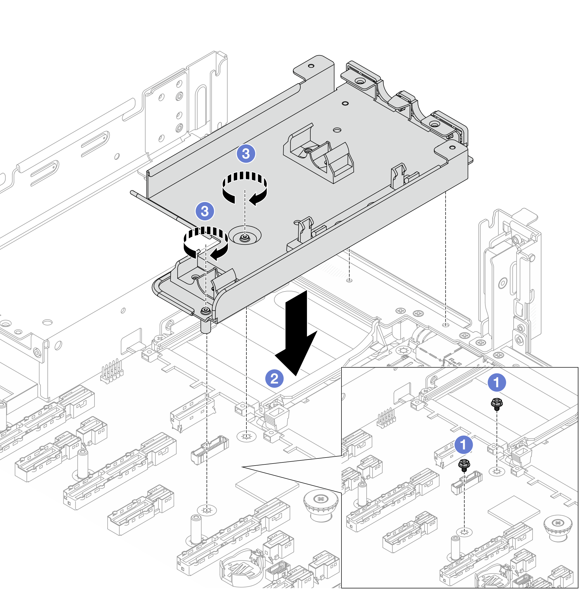
 Remove the screws on the system board assembly if needed.
 Align the screw holes in the hose holder with the screw holes on the system board assembly and the guiding pins on the holder with the holes on the rear wall.
 Install the screws to secure the hose holder to the system board assembly.
- Install the processor to the Processor Neptune Core Module. For more information, see Install a processor and heat sink.Figure 2. Installing the processor
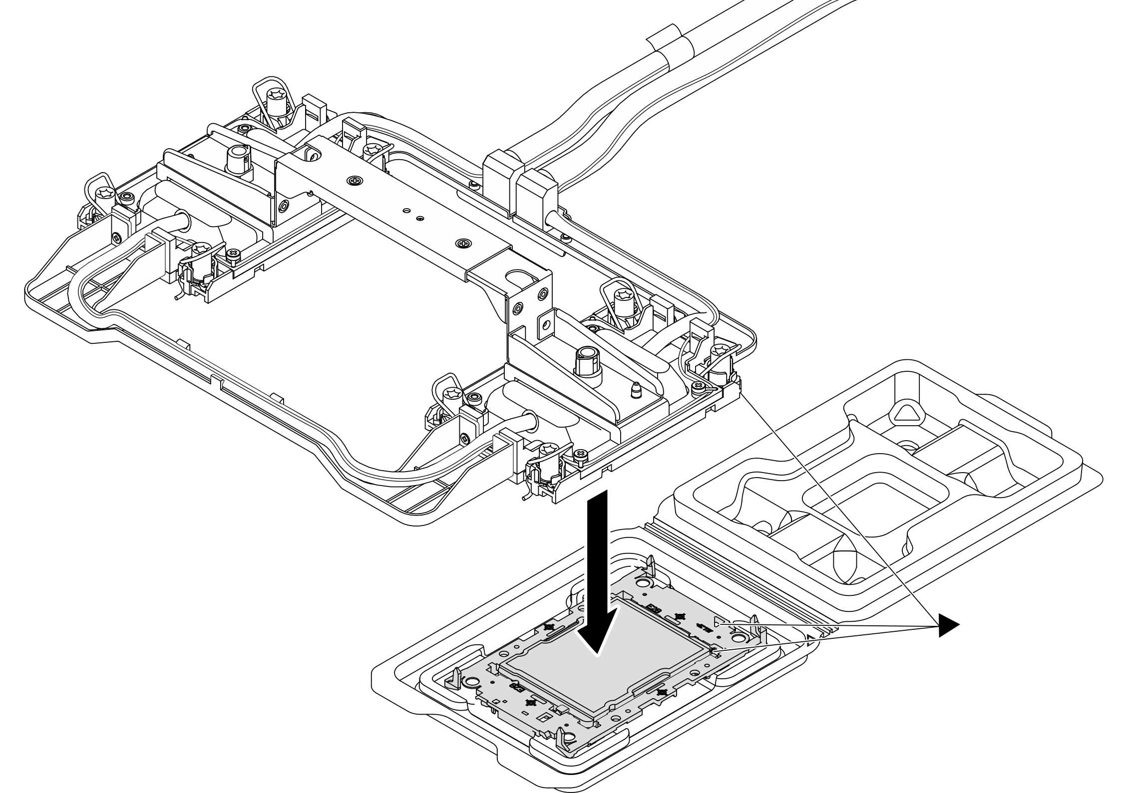
- Align the triangular mark on the cold plate assembly label with the triangular mark on the processor carrier and processor.
- Install the Processor Neptune Core Module onto the processor-carrier.
- Press the carrier into place until the clips at all four corners engage.
NoteIf the server has only one processor installed, generally processor 1, it is required to install a cover to the empty socket of processor 2 before proceeding with further installation.Figure 3. Installing the processor socket cover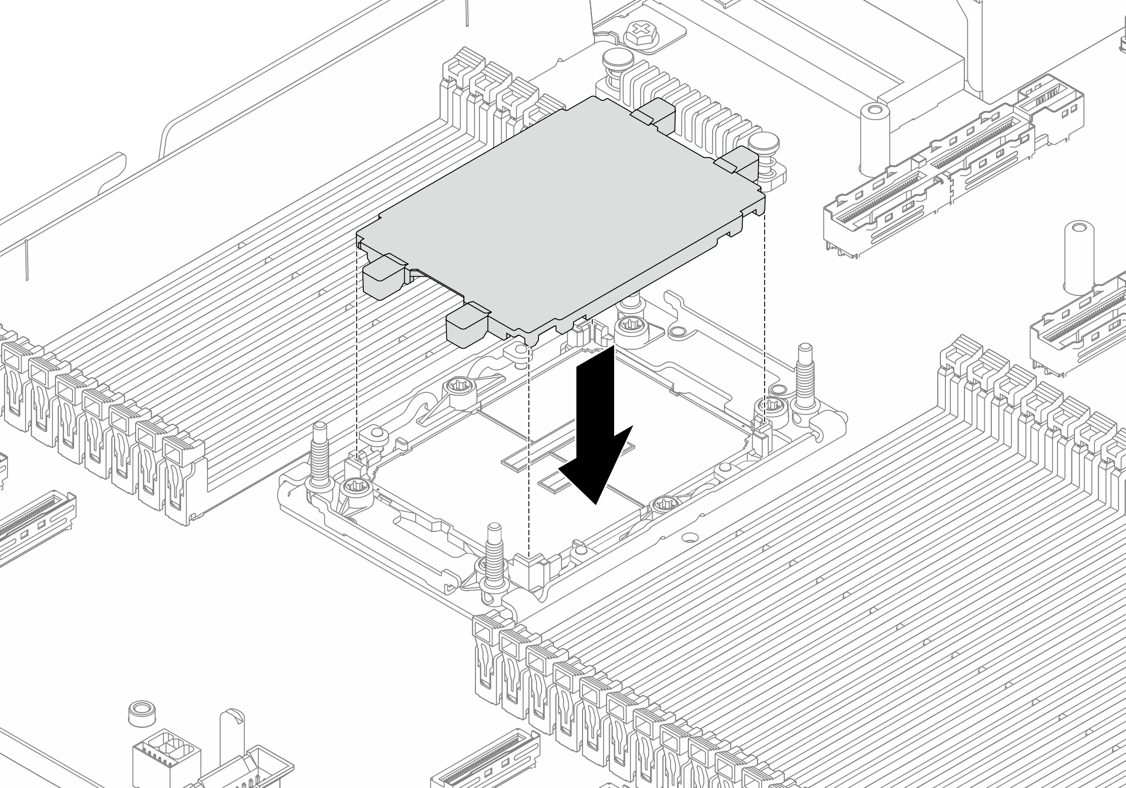
- Install the Processor Neptune Core Module to the system board assembly.Figure 4. Installing the Processor Neptune Core Module
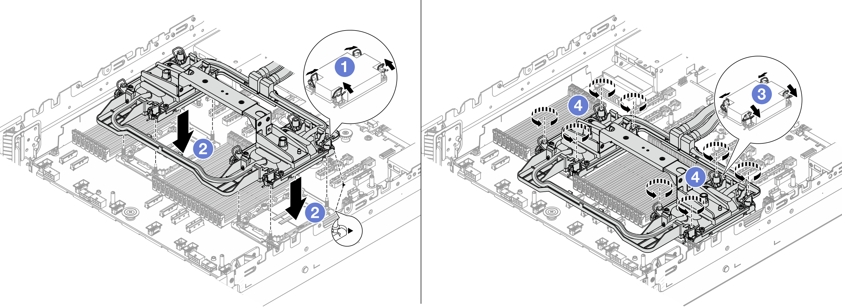
- Rotate the anti-tilt wire bails inward.
- Align the triangular mark and four Torx T30 nuts on the cold plate assembly with the triangular mark and threaded posts of the processor socket; then, insert the cold plate assembly into the processor socket.
- Rotate the anti-tilt wire bails outward until they engage with the hooks in the socket.
 Fully tighten the nuts in the installation sequence shown on the cold plate assembly. Tighten the nuts until they stop; then, visually inspect to make sure that there is no gap between the nut shoulder beneath the cold plate assembly and the processor socket. (For reference, the torque required to fully tighten the nuts is 10 +/– 2.0 lbf-in, 1.1 +/– 0.2 N-m.)
- Remove the handle from the Processor Neptune Core Module.Figure 5. Removing the module handle
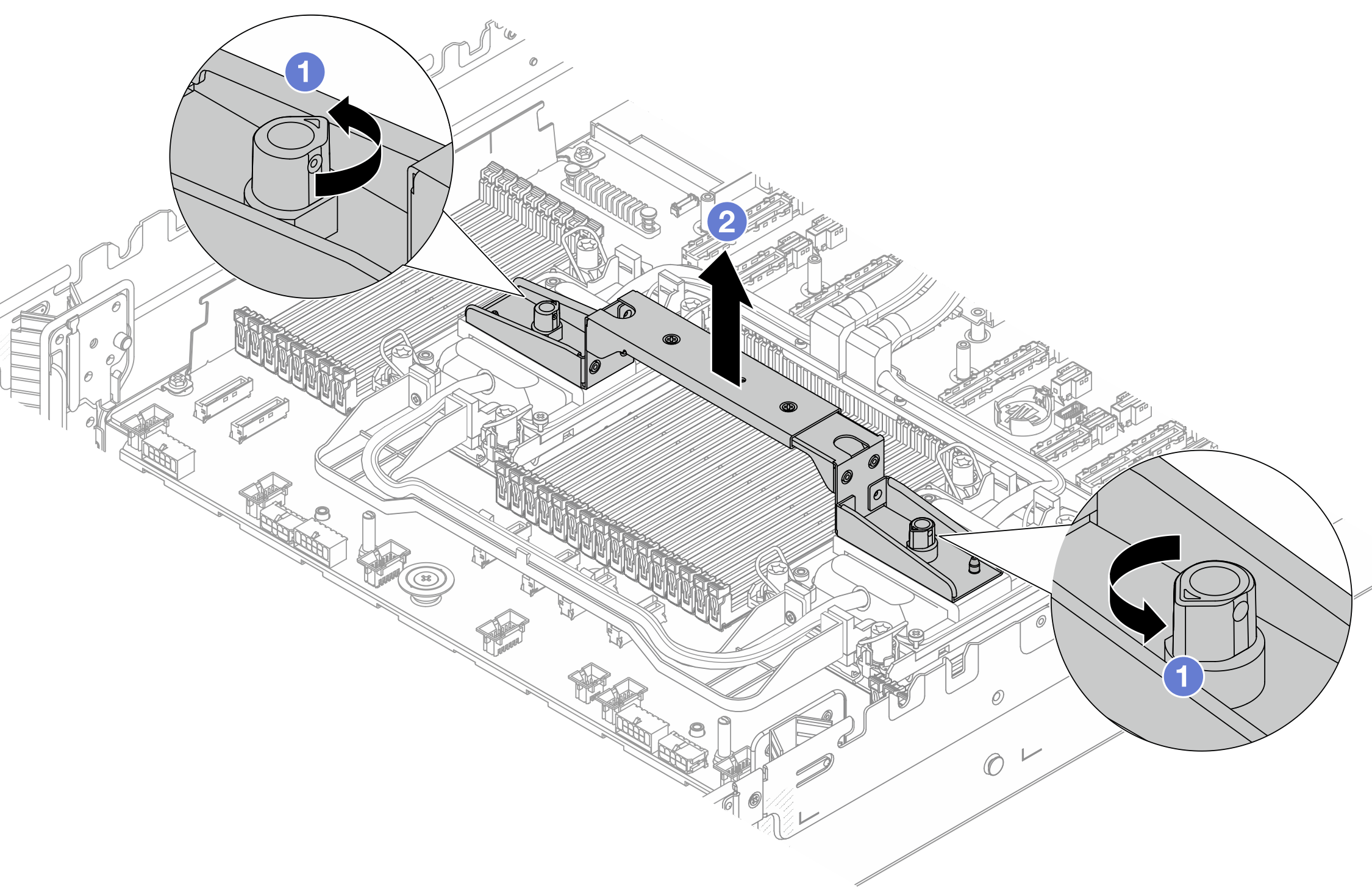
- Rotate the screws as illustrated above to unlock the handle.
- Separate the handle from the module.
NoteA newProcessor Neptune Core Module comes with a handle. To replace an old module with a new one, remove the handle of the new one as illustrated above.
To replace processors without changing the module, a handle is not needed. Skip 4 and proceed with further installation.
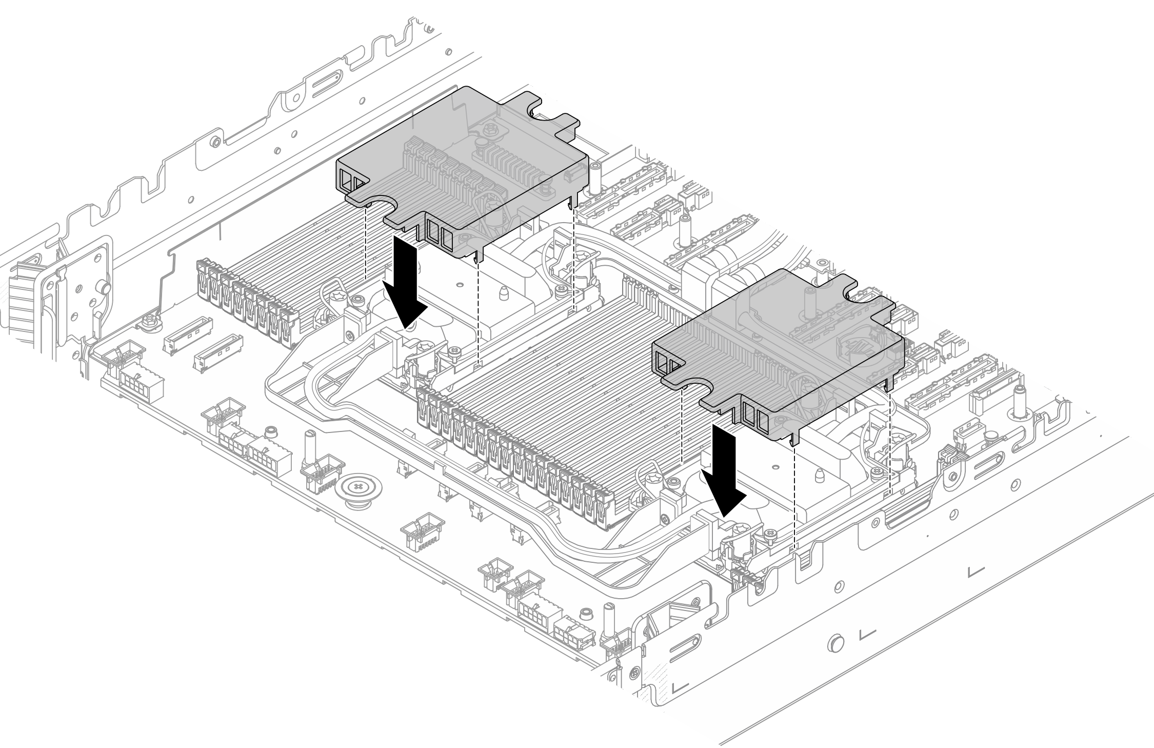
- Install the cold plate covers. Press the covers down as illustrated below.Figure 6. Installing cold plate covers
- Place the hoses and the liquid detection sensor module on the hose holder.Figure 7. Placing the hoses and liquid detection sensor module
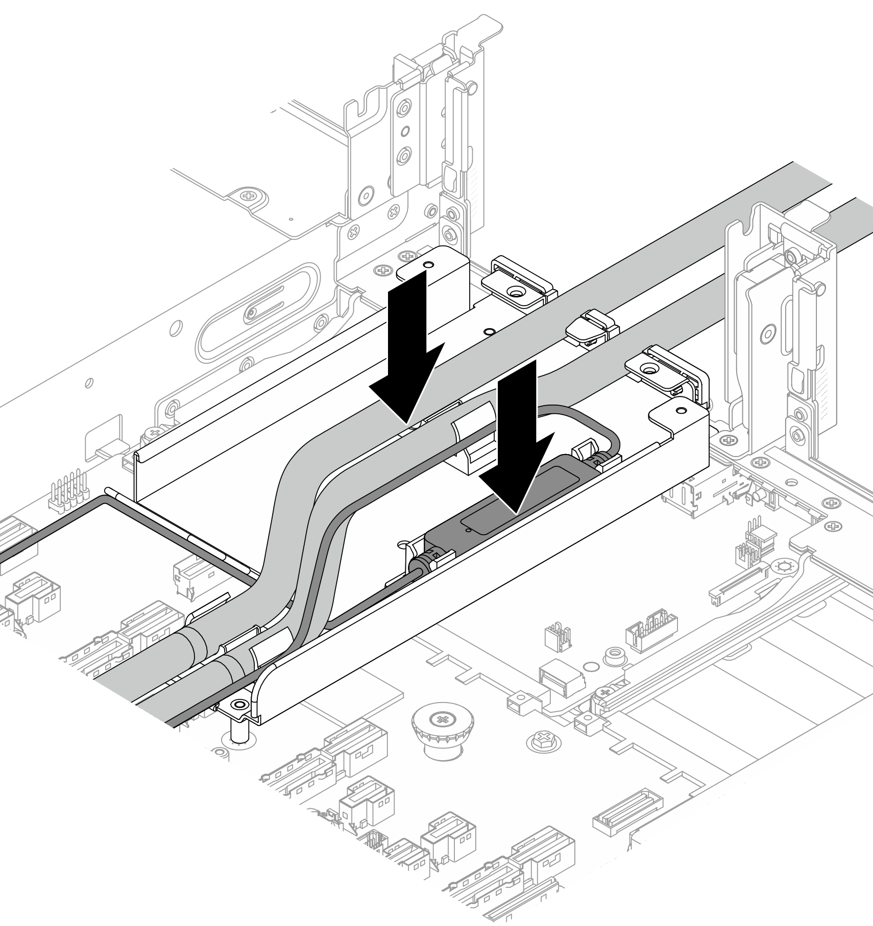 Figure 8. Installation details
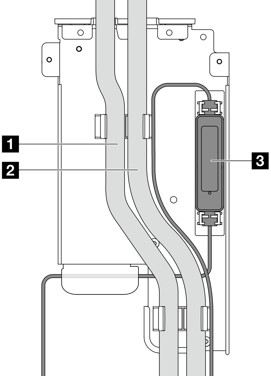
- 1 Outlet hose
- 2 Inlet hose
- 3 Liquid detection sensor module
NoteFor liquid detection sensor module working status, see LED on the leakage detection sensor module.
- Install the 1FH bracket or 3FH riser cage.
1FH bracket
Figure 9. Installing the 1FH bracket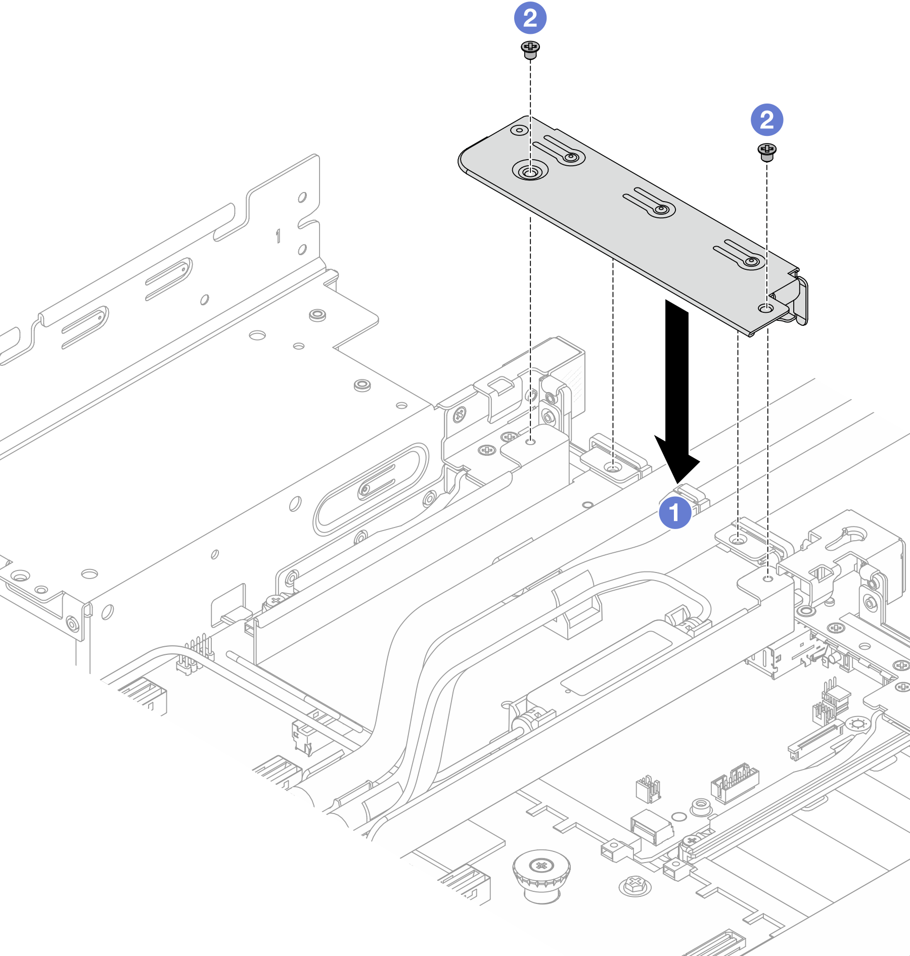
- Lower the bracket onto the hose holder.
- Install the screws to secure the bracket into place.
3FH riser cage
Figure 10. Installing the 3FH riser cage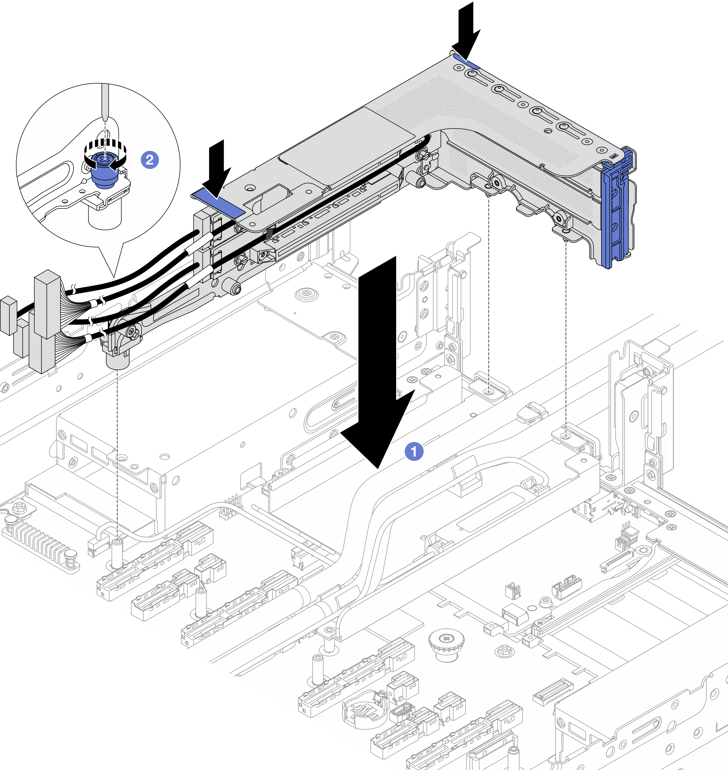
- Lower the riser cage into the chassis.
- Tighten the screw to secure the riser cage.
After you finish
Complete the parts replacement. See Complete the parts replacement.