24 x 2.5-inch front drive bays (NVMe)
This section provides cable routing information for the server model with 24 x 2.5-inch front drive bays (NVMe).
Note
The AnyBay backplanes are used as pure NVMe backplanes.
| Configuration | Mid or Rear BP | Storage controller | ||
| Qty. | Type | Qty. | Type | |
| Config. 1 | 3 | NVMe switch | ||
| Config. 2 | 4 | NVMe retimer | ||
| Config. 3 | 2 | Mid: 4 x 2.5'' NVMe | 4 | NVMe switch |
Depending on your server configurations, refer to one of the following sections for cable routing information.
Configuration 1 – 2:
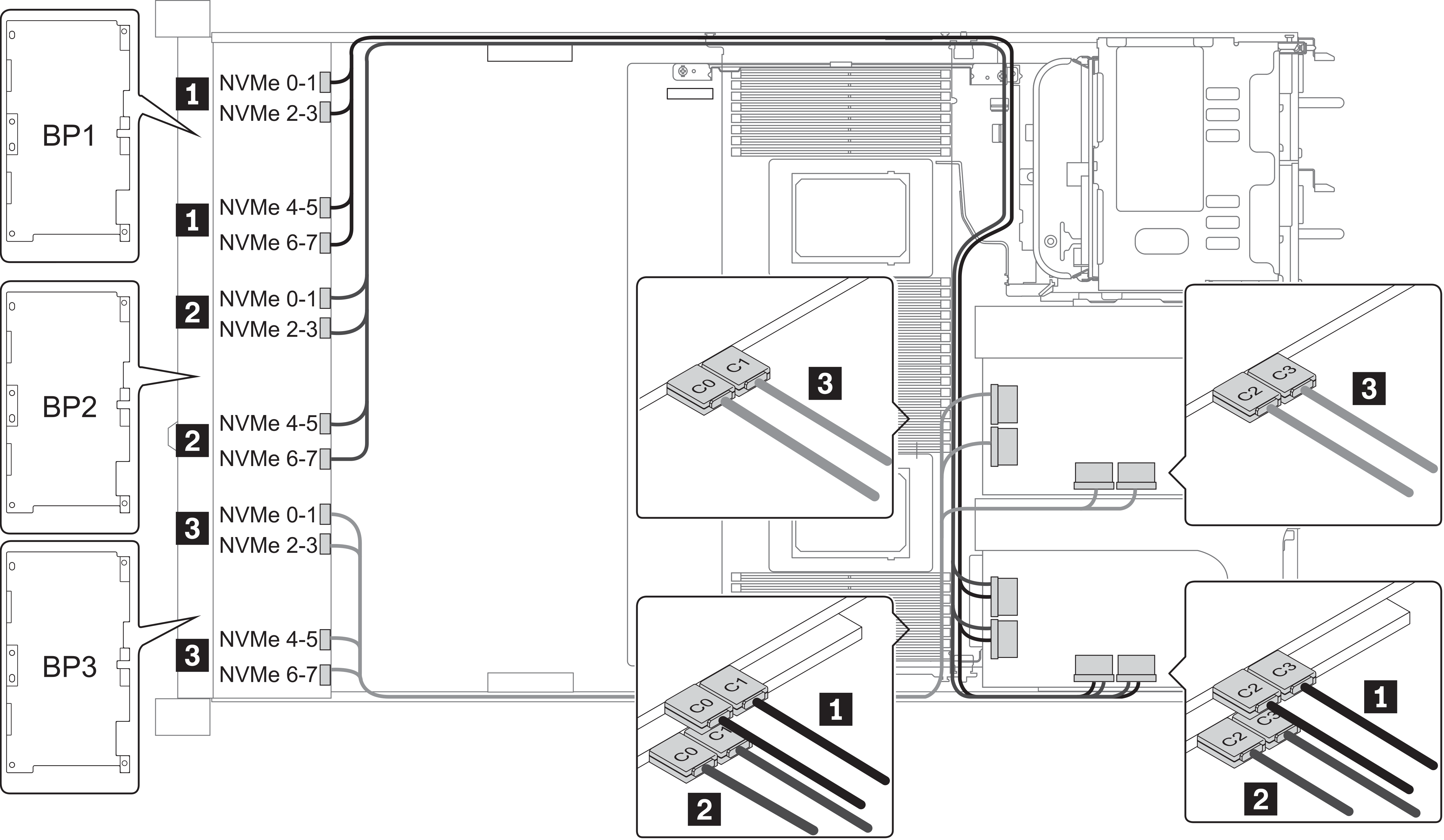
BP 1 + BP 2 + BP 3: 3 x 8 x 2.5-inch NVMe BP
| Config. | Front BP | System board | Storage controller | |
| NVMe switch | NVMe retimer | |||
| 1 | BP1: NVMe 0–1 BP1: NVMe 2–3 BP1: NVMe 4–5 BP1: NVMe 6–7 | Slot 1 C 0, C 1, C3, C4 | ||
BP2: NVMe 0–1 BP2: NVMe 2–3 BP2: NVMe 4–5 BP2: NVMe 6–7 | Slot 2 C 0, C 1, C3, C4 | |||
BP3: NVMe 0–1 BP3: NVMe 2–3 BP3: NVMe 4–5 BP3: NVMe 6–7 , | Slot 4 C 0, C 1, C3, C4 | |||
| 2 | BP1: NVMe 0–1 | PCIe 1, PCIe 2 | ||
| BP1: NVMe 2–3 | PCIe 3 | |||
| BP1: NVMe 4–5, NVMe 6–7 | Slot 1 C 0, C 1 | |||
| BP2: NVMe 0–1, NVMe 2–3 | Slot 2 C 0, C 1 | |||
| BP2: NVMe 4–5, NVMe 6–7 | Slot 5 C 0, C 1 | |||
| BP3: NVMe 0–1 | PCIe 7 | |||
| BP3: NVMe 2–3 | PCIe 8 | |||
| BP3: NVMe 4–5, NVMe 6–7 | Slot 4 C 0, C 1 | |||
Example
Figure 1. Configuration 1


Configuration 3:
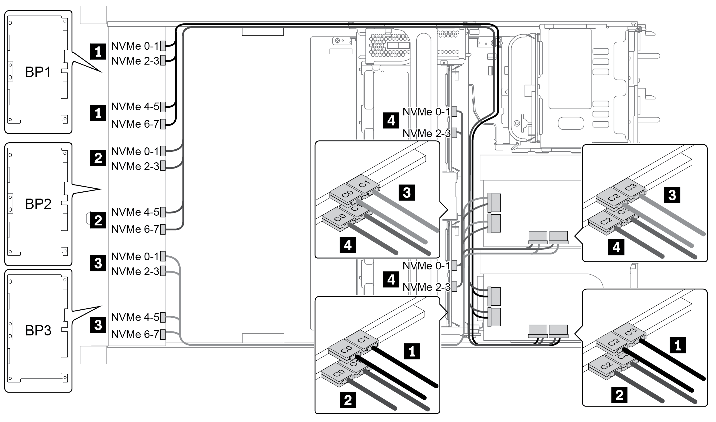
BP 1 + BP 2 + BP 3: 3 x 8 x 2.5-inch NVMe BP
BP 5+BP 6: 2 x 4 x 2.5'' NVMe BP
| Config. | Front BP | Mid BP | Storage controller |
| NVMe switch | |||
| 3 | BP 1: NVMe 0–1, NVMe 2–3NVMe 4–5, NVMe 6–7 | Slot 1 C 0, C 1, C 2, C 3 | |
| BP 2: NVMe 0–1, NVMe 2–3NVMe 4–5, NVMe 6–7 | Slot 2 C 0, C 1, C 2, C 3 | ||
| BP 3: NVMe 0–1, NVMe 2–3NVMe 4–5, NVMe 6–7 | Slot 4 C 0, C 1, C 2, C 3 | ||
BP 5: NVMe 0–1, NVMe 2–3 BP 6: NVMe 0–1, NVMe 2–3 | Slot 5 C 0, C 1, C 2, C 3 |
Example
Figure 2. Configuration 3


Give documentation feedback