Install the SXM GPU board
Follow instructions in this section to install the SXM GPU board.
About this task
Removing and installing this component requires trained technicians. Do not attempt to remove or install it without proper training.
Read Installation Guidelines and Safety inspection checklist to ensure that you work safely.
A torque screwdriver is available for request if you do not have one at hand.
- Hold the long sides of the SXM GPU board with two hands while removing the new GPU board from the package box.Figure 1. Removing SXM GPU board from the package box
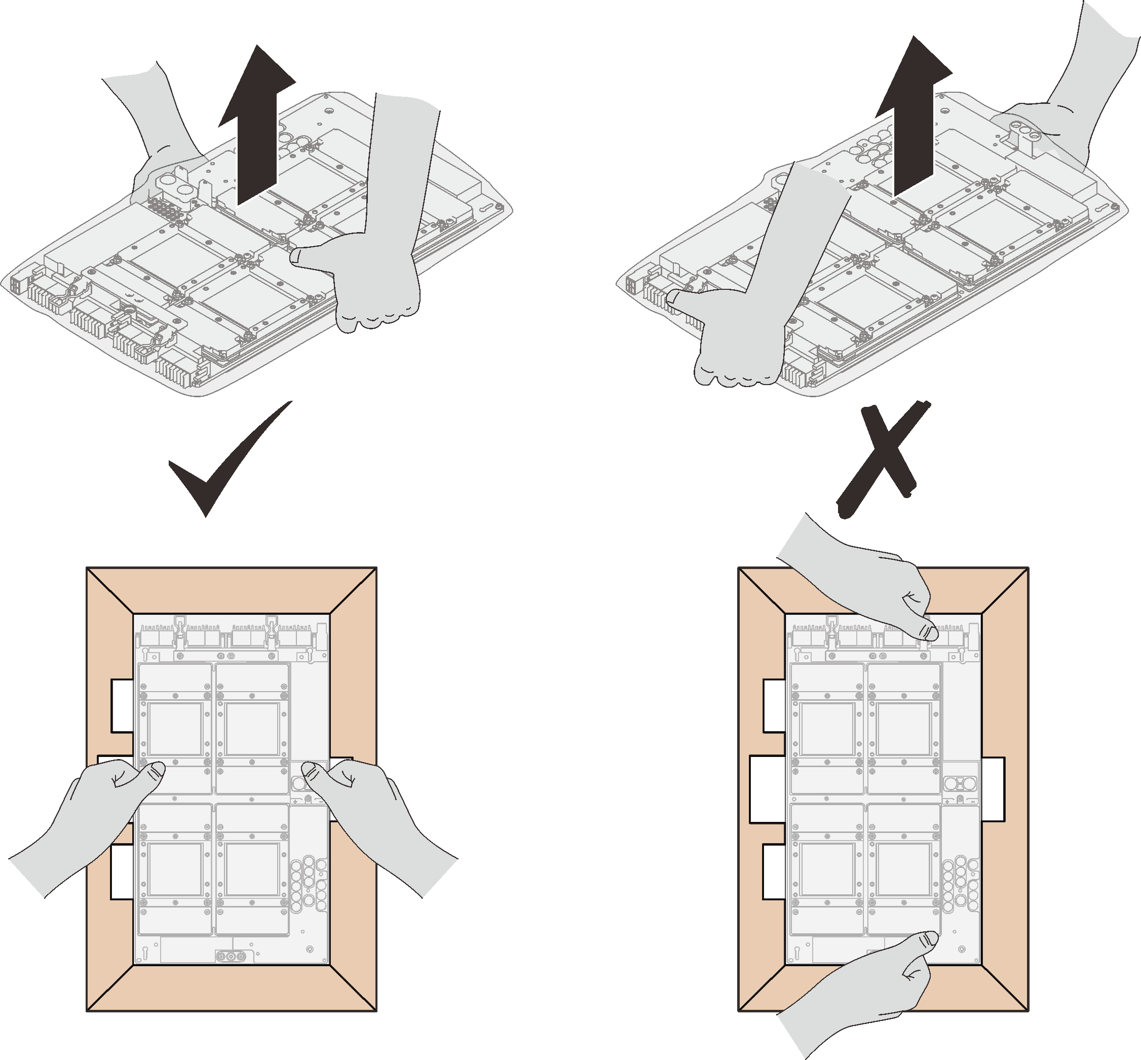
Once the SXM GPU board is removed from the plastic protective bag, hold two handles with both hands to move the GPU board.
Figure 2. Removing SXM GPU board from the package box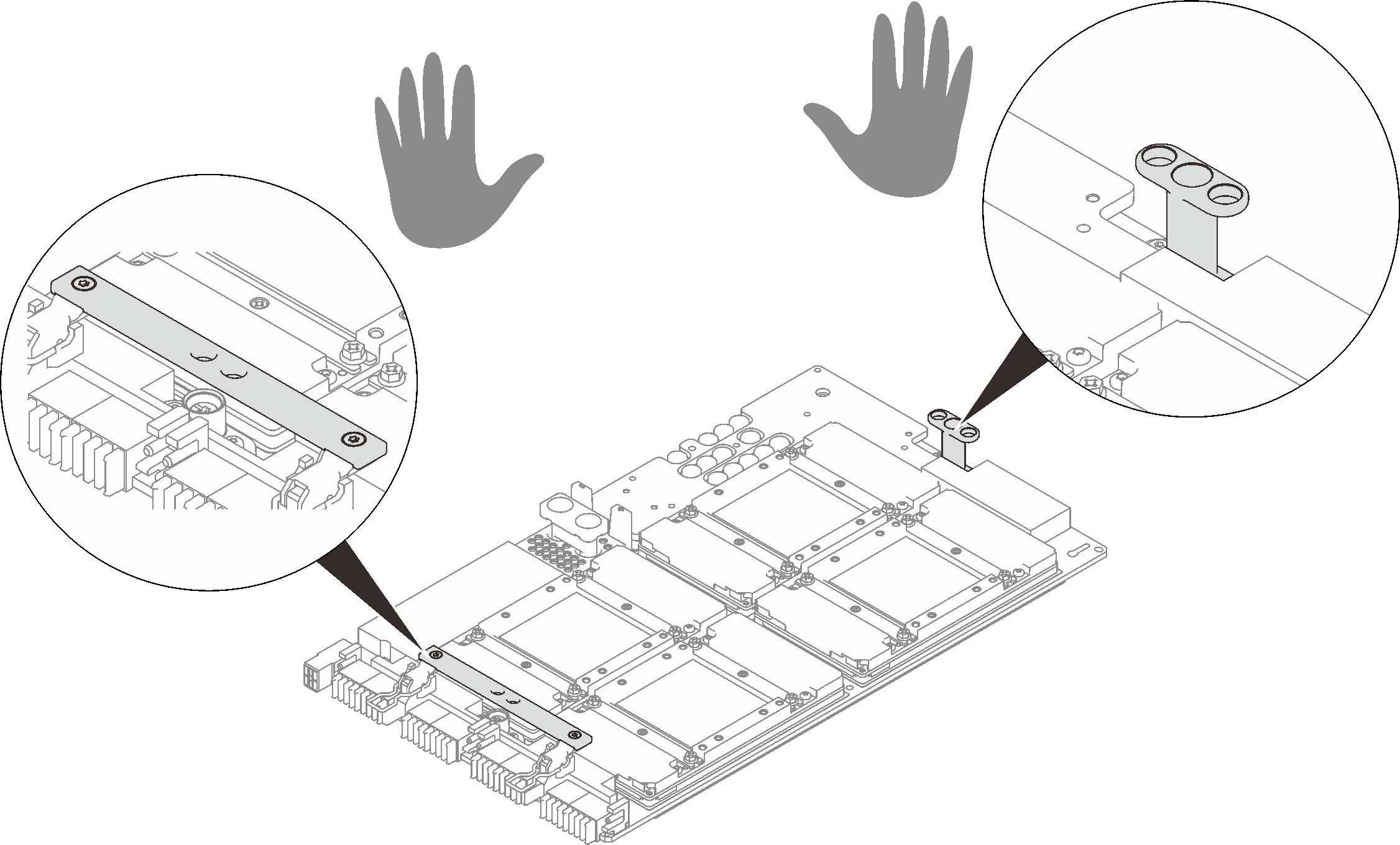
| Torque screwdriver type list | Screw type |
| PH 2 head screwdriver | Four Philips #2 One Phillips #2 screw (18mm) |
| Torx 10 screwdriver | Torx T10 screw (captive screw) |
Procedure
- Hold the SXM GPU board handles and align the SXM GPU board with the four guide pins on the GPU tray; then, gently place the SXM GPU board down into the tray.Figure 4. Placing the SXM GPU board into the GPU tray
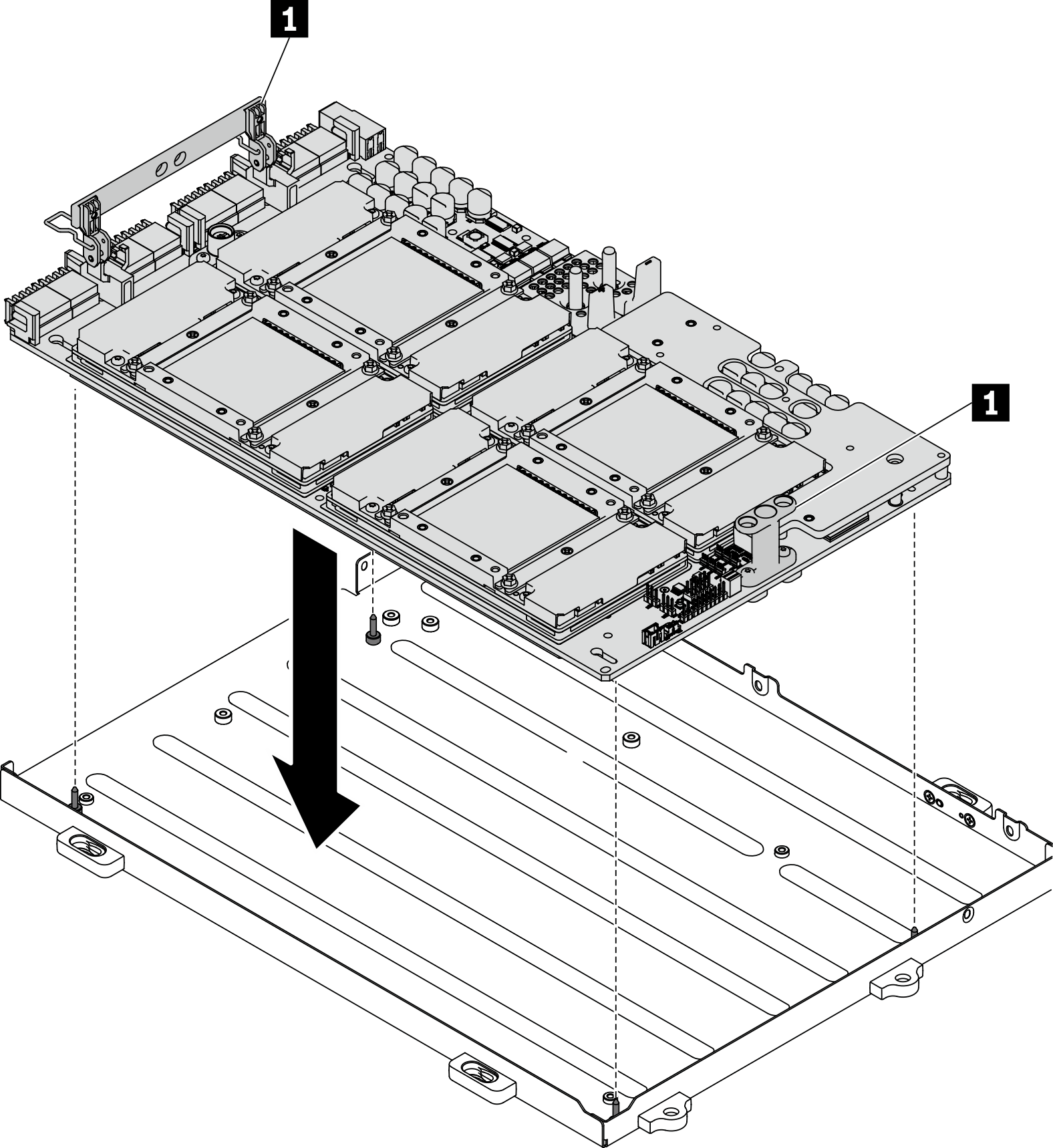
1 SXM GPU board handle - With a PH 2 head screwdriver, fasten the five screws that secure the SXM GPU board to the GPU tray. Then, with a Torx T10 screwdriver, fasten the two captive screws on the SXM GPU board handles. Remove the screws with a torque screwdriver sets to the proper torque. For reference, the torque required for the screws to fully tighten/removal is 0.6±0.06 newton-meter, 5±0.5 pound-inch.AttentionMake sure to install the Phillips #2 screw (18mm) to the designated screw hole. See the following illustration for the screw hole location.Figure 5. Installing the SXM GPU board
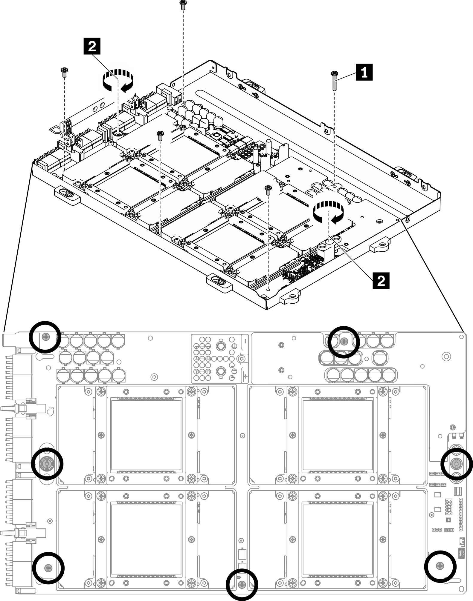
1 Phillips #2 screw (18mm) 2 Torx T10 screw (captive screw) - Apply new thermal grease to the SXM GPU board.
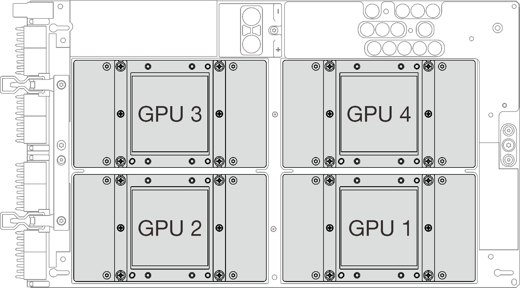
- If you have cleaned the top of the GPUs with an alcohol cleaning pad, make sure to apply the new thermal grease after the alcohol has fully evaporated. Apply new thermal grease (1.5 g) to the top of each of the four GPUs.Figure 6. Thermal grease application
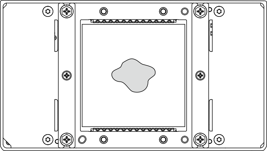
- If you have cleaned the top of the GPUs with an alcohol cleaning pad, make sure to apply the new thermal grease after the alcohol has fully evaporated. Apply new thermal grease (1.5 g) to the top of each of the four GPUs.
After you finish
Follow the instructions below to install the L2A.
Lift up the cold plate.
 Slightly lift up the cold plate with your right hand, and hold the cold plate assembly lifting handle with your left hand from underneath the cold plate.
 Remove your right hand from the cold plate while holding the cold plate assembly lifting handle with your left hand.Figure 7. Lifting up the cold plate
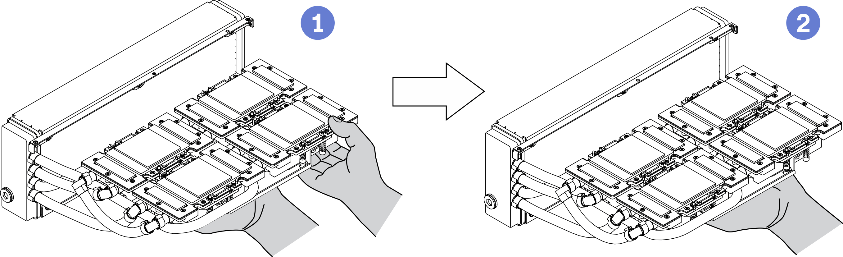
Rotate the L2A clockwise.
Hold the bottom edge of the radiator, and hold the cold plate assembly lifting handle from underneath. Rotate the L2A clockwise so that the left end of the radiator is standing on the flat surface, and the cold plate assembly lifting handle is facing your left side. Move your right hand to hold the right end of the radiator which is attached with the tubes.Figure 8. Rotate the L2A clockwise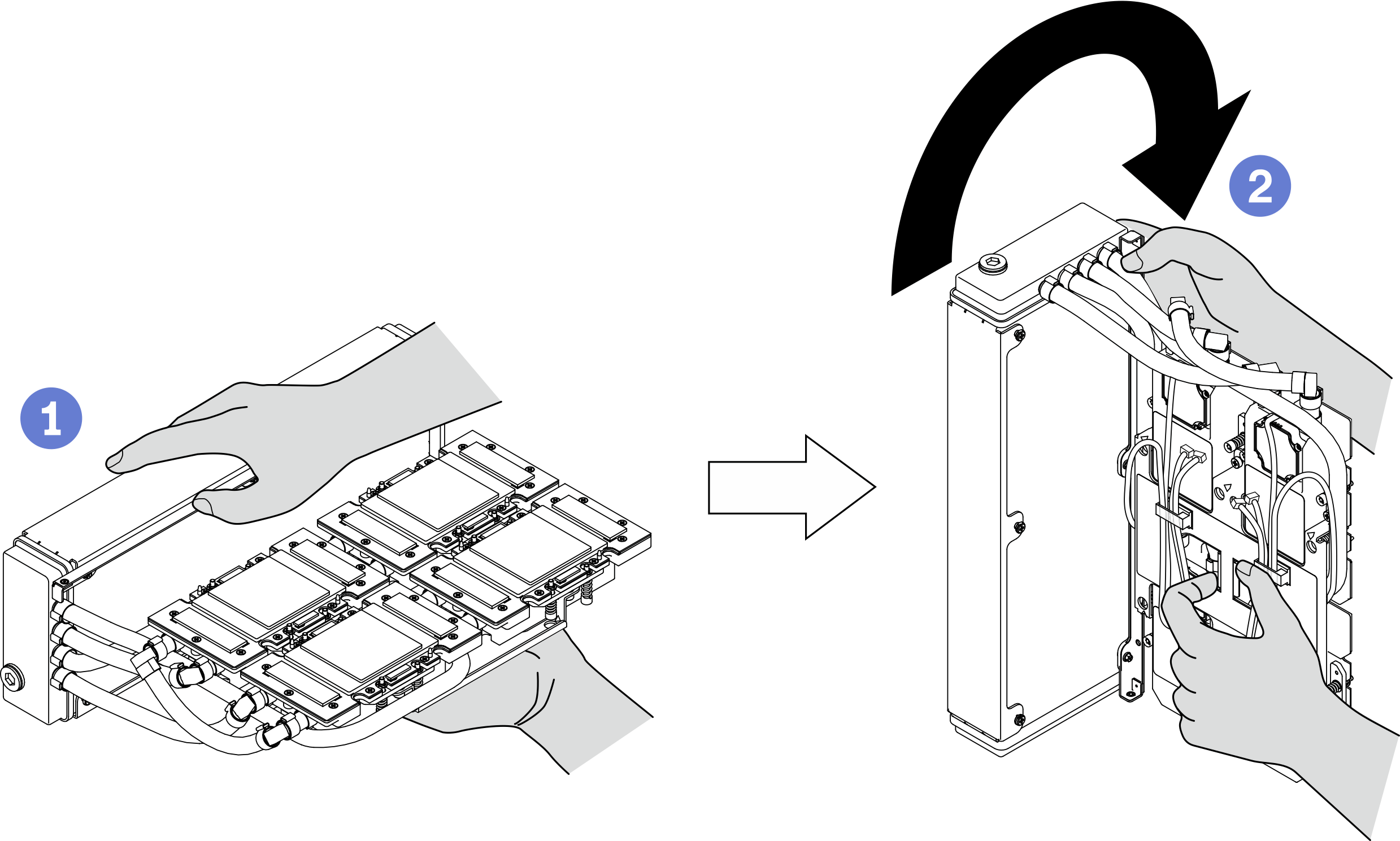
Turn the L2A upside up.
Hold the right end of the radiator which is attached with the tubes, and hold the cold plate assembly lifting handle. Rotate the L2A clockwise so that the upper side of the radiator and cold plate assembly lifting handle are facing up.AttentionTo preventcold plate assembly thermal grease from contacting the flat surface below, lift up the cold plate assembly before installing it onto the SXM GPU board. Figure 9. Turning the L2A upside up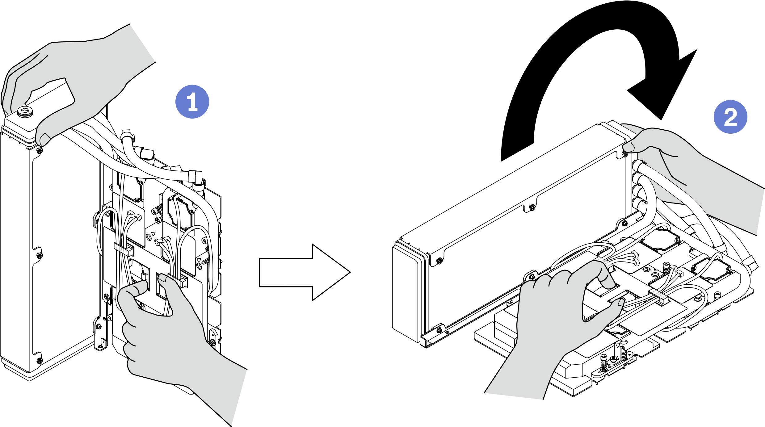
Reinstall the L2A. See Install the Lenovo Neptune(TM) liquid-to-air (L2A) hybrid cooling module.
Reinstall the retimer assembly. See Install the retimer assembly.
Reinstall the front I/O expansion board module. See Install the front I/O expansion board module.
Reinstall the network adapter. See Install a network adapter.
Reinstall the 2.5-inch drive cage assembly. See Install the 2.5-inch drive cage assembly.
Complete the parts replacement. See Complete the parts replacement.
Demo video